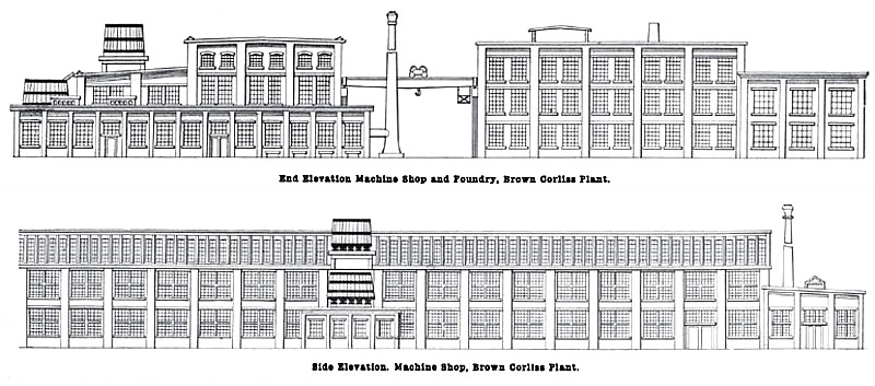
The accompanying drawings give an outline plan and elevations of the new plant of the Brown Corliss Engine Co. The shops are located at Corliss, Wis., on the main line of the Chicago, Milwaukee 8: St. Paul Ry., and about 23 miles south of Milwaukee. The machine shop and foundry buildings run north and south, the machine shop being on the west side of the foundry, with a space of 65 feet between them. It was the company's purpose to design a plant in which a high class of engine work could be done with a minimum cost of production, and with that end in view a great deal of attention has been given to every detail covering both the arrangement of the buildings and also the type and arrangement of the tools.
The plant is located at some distance from other buildings, so that lighting conditions are practically perfect.
The machine shop and foundry are constructed of steel with brick walls. The pattern shop and the pattern storage building, offices, forge, boiler and engine rooms are also of brick.
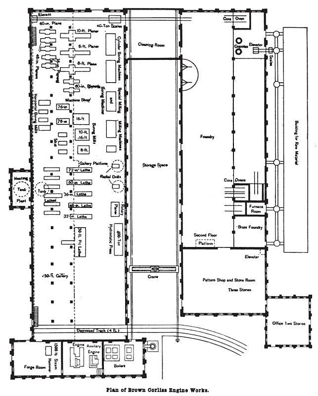
Referring to the general plan, it will be noticed that the raw material, such as pig iron, coke, moulding sand, etc., are brought in on the east side of the foundry on the railroad siding, and is distributed into the proper bins in the storage building. Between this building and the foundry is a system of narrow gage track, which distributes the raw material to the proper point in the foundry.
The cupolas are located at the east side and at the north end of the foundry, so that when the foundry is extended the cupolas will be practically in the center of distribution.
There is a 45-foot wing on one side of the foundry, which is equipped with 15-ton cranes, having a clear lift of 18 feet under the hook. This wing will be used for the light and medium class of castings. The main portion of the foundry has a span of 70 feet and is equipped with two 30-ton electric cranes with auxiliary hoists of 5 tons capacity. These have a clear lift of 28 feet under the hooks. The foundry is no feet wide and 325 feet long.
The pattern shop and the pattern storage building are at the south end of the foundry, being 110 feet in length and 80 feet in width. The lower story will be used for the storage of large and heavy patterns. The second story is a pattern shop, and the third and fourth stories are for the storage of the medium and small size patterns. For the convenience of handling the finished patterns, a platform is extended out underneath the cranes so that the patterns can be moved from the pattern shop on this platform, from where they can be handled by the cranes in the foundry. For the convenience of handling the heavy patterns, suitable cranes are provided in the storage building.
Between the foundry and the machine shop there is a space of 65 feet, this space being served by a 30-ton electric crane, which travels the full length of the two buildings and also passes over the railroad track. This space will be used for the storage of flasks and any finished product, which it may be necessary to hold for shipment.
Whenever it is necessary to store any finished product it is done by lowering it on a car at the south end of the machine shop, the car then being run out under the yard crane, which will pick up the work and store it in any part of the space between the two buildings. When shipment is required it is only necessary to pick up the parts and load them on cars which stand within the sweep of the crane.
The section of the machine shop building is similar to that of the foundry. The gallery in the machine shop is made of double width and is placed on one side only instead of being half the width and placed on both sides. This arrangement of buildings was decided upon owing to the fact that the wider space could be used more advantageously than could possibly be done with the narrow wings on either side of the buildings. This arrangement
also has the advantage that better light can be gotten on all sides of the buildings and better provision can be made for crane service between the two buildings.
The machine shop has a span in the main part of 65 feet, and is equipped with two 30-ton cranes with 40 feet clear lift. Under the gallery floor is a 10-ton crane, which runs the entire length of the shop. The gallery is 53 feet wide in the clear, and is especially suited to the medium and lighter class of work.
Particular attention has been given to the matter of lighting, and a very large amount of glass is provided for, ribbed glass being used throughout.
The forge room, engine room and boiler room are located at the south end of the machine shop. Ample room has been provided in the engine room and boiler room to increase the power plant.
The machine shop is 440 feet long and 118 feet wide, provision being made on the north end to extend the shop to any length desired. In the arrangement of tools the group plan has been carried out as far as possible, that is, the planers are in one group, the boring mills in another, and so on, in order to have all operations of the same land done in a particular part of the shop.
In equipping the shop with tools only those of recent design and of heavy pattern were selected, so as to secure high cutting speeds and rapid machining, and no tools were purchased which would not in every way fulfil the most rigid specifications.
When the matter of transmitting power to the tools was first taken up, it was found that no really satisfactory method had been developed, and a great deal of time was devoted to investigating and developing a method in advance of anything then in use. It was decided to adopt the multiple voltage system as being the most elastic and best adapted to machine shop purposes. The motors have a variable speed of 6½ to 1, this range being accomplished by using a minimum voltage of 60 and maximum of 250, with intermediate voltages of 80, 110, 140 and 190. It has been the usual arrangement of variable speed motors to make use only of the speeds corresponding to the various voltages, with no provision for subdividing the change in speed from one voltage to another. With this latter arrangement the faults of the stepped cones and belted arrangements were retained.
In the existing arrangement of the motors this trouble has been obviated by using a controller which will divide the range of speed between each voltage into six parts, so that if the greatest change of speed from one voltage to another is 30 per cent, this is divided up into six parts, and practically a continuous range of speeds is provided from the minimum to maximum. No armature resistance is introduced to change the speed of the motor, but the whole change is gotten by the field resistance.
Speed curves of the various tools show a very perfect range of speeds. The Bullock Electric Mfg. Co., of Cincinnati, Ohio, are furnishing the entire outfit of motors, and have given this equipment great attention in order to be able to furnish a drive which would meet all demands. It was not thought feasible to carry the electric drive to the extent of driving all of the small tools by individual motors and these tools have been grouped in 18-horsepower units.
The large tools and erecting floor will be served by two Pawling & Harnischfeger 30-ton electric cranes equipped with 5-ton auxiliary hoists, it being the purpose to use the auxiliary hoists for all work up to their capacity, as the hoisting speeds are very much higher than provided for the 30-ton hoist, the hoisting speed of the auxiliary being 50 feet per minute.
The cranes will have a bridge speed of 500 feet per minute, and have been designed especially for rapid service. Wherever it is found necessary to serve large tools with individual cranes, air hoists are used and compressed air will be very largely used throughout the shop and foundry.
The power plant is composed of two direct connected units, one of 125-kilowatt capacity, the other of 250-kilowatt capacity, it being the intention to use the smaller unit as an auxiliary. The 125-kilowatt unit is of the non-condensing compound type, making 250 revolutions per minute. The 250-kilowatt unit will be of the company's own make of the cross compound non-condensing type, and will make 140 revolutions per minute. There are two 175-horsepower water tube boilers supplying steam of 150 pounds pressure. There will be no shafting in the engine room, the transmission of power being entirely electrical.
An elevated track on a substantial trestle is located close to the boiler house and provision is made for delivering the coal directly in front of the boilers. A storage capacity of 500 tons has been provided. Raw material, such as bar iron, etc., for the forge room, will come in on this elevated track.
The buildings are heated by the Sturtevant hot air system, the apparatus being furnished by the National Blower Co. of Milwaukee, and is installed under a guarantee to properly heat the building with steam of atmospheric pressure. The exhaust steam from the engines will be used as far as it will go, using live steam to make up any deficiency, this steam being reduced to atmospheric pressure before entering the heating system. The exhaust steam will pass through a 400-horsepower Colles heater before entering the heating system. A special heater has been designed for meeting the requirements of the plant, so as to do away with all turns in exhaust piping wherever possible.
The plant was designed and erected under the supervision of Walter S. Whiting, vice president and treasurer, and W. F. Brown, second vice president and general manager.
The location of the shops at Corliss affords the best railroad facilities, besides being exceptionally convenient for visiting patrons, as all trains between Chicago and Milwaukee stop at this point.
In 1874, Parkersville, Wi was founded by S. Parker. Some time later the town was renamed Western Union Junction. The village was surveyed on Aug. 13, 1901, and name of the village was changed to Corliss for the Brown Corliss Engine Company of Milwaukee. On July 20, 1907 the recession set in, causing the filing of bankruptcy by the Brown Corliss Engine Company. In 1907 the company rentered bankruptcy and reorganized as the Wisconsin Engine Co. The 1909 catalog was issued in the name of Wisconsin Engine Co. The firm went into bankruptcy in 1917 and closed the plant.
The B. F. Sturtevant Company of Boston, Massachusetts bought the factory in 1923 and on October 2, 1923, the name of the village was changed from Corliss to Sturtevant, WI.
Information Sources
- The Engineer, V39, 01 Jan 1902, pgs. 42-43
- More history and machine information can be found at the Sturtevant WI Factoryweb page.