|
Title: |
1880 Article-Bliss & Williams, Double Acting Cam Drawing Press |
|
Source: |
American Machinist, 31 Jan 1880, pg. 1 |
|
Insert Date: |
7/2/2015 12:38:17 PM |
Bliss & Williams Drawing Press
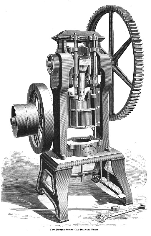
The engraving on this page represents a new double-acting cam-drawing press, which has just been produced, and is now being manufactured by Bliss & Williams, Plymouth and John Streets., Brooklyn, N. Y.
This press is used for the purpose of forming or drawing pans, such as wash-basins, bread-pans, and other small wares, each from a single sheet of tin. It consists of two upright columns joined to each other by a strong base which is mounted upon a suitable bed.
A steel shaft with journals 3¾" diameter is located at the top; upon which are placed two steel cams of irregular shape, each having a face 3" wide. These cams are fitted upon the oval or oblong shape, formed by the shape of the crank, the advantage of this being that the bearings can be brought nearer together, thereby avoiding the difficulties arising from springing of the shaft. In this case the crank is 6" in length, and 3¾-" diameter. The two cams located on either side of the crank are 3" wide, and the distance between the journals is only 14½".
The lower part of the frame has an opening 24", to the sides of which V guides are attached for a cylindrical cross-head. This cross-head is suspended from yokes placed upon the cams, by means of guide-rods, which are provided with threads and nuts by which the crosshead may be adjusted up or down. The yokes upon the cams are furnished with four steel rollers 4½" in diameter, located at the top and bottom of each cam. These rollers are bushed with gun metal, and run upon steel pins.
The bottom flange of the cross-head has holes through it for holding the pressure plates.
The solid cross-head for holding the stamping dies works in box-guides within the cylindrical cross-head. The latter is connected with the crank by means of an adjustable connection, which is simply a screw and jam nut. The lower end of this connection is a ball and socket joint, arranged to move freely without lost motion. If any lost motion does appear it can be readily taken up.
This press is strongly geared, the diameter of the large gear being 60", and the pinion 8", which is as seven to one, and has a steel shaft 3" diameter on the back part, upon which is placed a heavy fly-wheel 45" in diameter, weighing 750 lbs. The tight and loose pulleys are 20" diameter, and have a 6" face.
The operation of this press is as follows: The bottom die having been put in place, is held by four bolts, while the top die, which has a tapped hole in the center is firmly screwed upon a stud, which projects from the bottom of the cross-head. A pressure plate with an opening just allowing the solid die to pass through it, is then attached to the cylindrical cross-head, and a sheet of tin of the required dimensions is placed upon the bottom die. When the press is started the pressure plate quickly descends upon the tin, and holds it fast, when the solid die upon it, and draws the metal between two surfaces. The pressure plate prevents the plate from pleating and makes it form smoothly.
Straight-sided pans 14” in diameter, and 4" deep, may be formed at one operation upon this press, while wash-basins, and other irregular forms require two operations.
The machine will make from twenty to twenty-five strokes per minute. The stroke of the forming die on this machine is 8", and that of the pressure plate 4".
A noticeable feature about the machine illustrated is, that the irregular-shaped cams exactly fill the space between the rollers (located at the top and bottom) at all points of the stroke which allows no lost motion.
A brake is applied at the end of the crankshaft as shown, in order that all the joints may be allowed to work freely without producing an unsteady motion, before the die touches the work placed under it. This brake is lined with leather to prevent wearing or cutting the parts.
A treadle placed under the machine is connected with an ingenious clutch, which is used for starting and stopping the machine. It is so arranged, that, when the press is started by pressing the foot upon the treadle, the die will make one stroke, and stop of itself at the upper end of the stroke.
This clutch consists of a piece of steel fitted into a half-round groove in the face of the journal, which is pivoted at each end.
When the press is at rest this piece of steel forms a part of the journal, but when it is desired to start the press this piece of steel is rolled by a small arm, and forms a projection across the face of the journal, which engages a groove in the large wheel which is faced with steel.
When the stroke is completed, the small arm referred to comes in contact with a tripping device, which rolls the clutch back to its former position, thus stopping the press.
There are three points in the course of the stroke at which the clutch, will take effect, thus saving the time which would be lost if only a single position could be used. The parts that are used in starting and stopping are cushioned by springs, so that most of the wear-and-tear, besides unnecessary noise, is thereby avoided. All parts are made to gauges, and the workmanship is characteristic of the well-known firm referred to. |
|
 1880 Bliss & Williams, Double Acting Cam Drawing Press
|
|