|
Title: |
1869 Article-Aveling & Porter, Agricultural Road Locomotive |
|
Source: |
Recent Improvements in the Steam Engine, 1869, pg. 271 |
|
Insert Date: |
2/5/2015 9:54:43 PM |
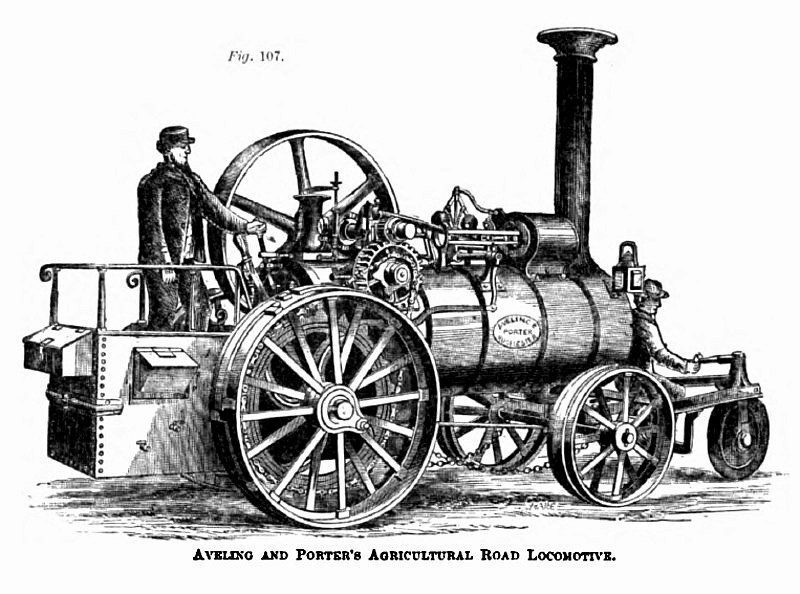
Aveling's Patent Agricultural Road Locomotive, designed for steam cultivation, threshing, sawing, and removing agricultural produce, is represented in fig. 107. The boiler, like that already described, is unusually large and is flush; it is clothed with hair felt, lagged and covered with sheet-iron from end to end. The cylinder and working parts are like those of the engine intended exclusively for traction purposes. The gearing, however, is single, and for one speed only. There is a pinion on the end of the crank shaft, working into a spur wheel on a stud below; and on this wheel is cast a chain pinion to take in the endless pitch chain. This gearing works on the stud in a curved slot in the lower part of one of the crank shaft brackets, struck from the centre of the crank shaft. In the side of the bracket is an adjusting set screw, working through a tapped boss, and bearing at its inner end against the side of the stud shaft. By turning this screw the stud shaft may be caused to slide laterally in the curved slot, as this slot in the bracket is cut from the centre of the crank shaft, and by this arrangement the stud shaft may be adjusted to any desired amount, so as to tighten up the driving chain without interfering with the gearing together of the spur wheel on the stud and the pinion on the crank shaft.
The spur wheel receives motion from the pinion, which slides laterally by means of a groove and feather on the end of the crank shaft, but always revolves with the shaft. The object of this lateral adjustment of the pinion is to throw it in or out of gear with the spur wheel, so that, when the engine is not required to travel over the ground, the locomotive gear may be thrown out of action; and the engine can then be immediately employed to drive ploughing, threshing, sawing, or any other machinery, in the same manner as ordinary stationary or portable engines.
On the axle of the road wheels is a large chain wheel, round which and the chain pinion an endless chain passes, connecting it to the driving gear already described.
The road or driving wheels are loose on the axle, but are driven by a bolt passing through a boss on the nave and through the chain wheel on the one side, and on the other through a hole cast in the friction break, which, like the chain wheel, is keyed upon the axle. The object in connecting the wheels with the driving gear in this manner is to enable either wheel to be readily disconnected, which is a great advantage in turning very sharp curves. But a self-acting clutch may also be used for this purpose. The driving or road wheels are 5 ft. 6 in. in diameter, and 16 in. broad on the face; there is a 5 ft. fly-wheel for driving machinery when the engine is disconnected from the locomotive gearing. There are now many of these engines that have traveled from 4,000 to 6,000 miles, moving from farm to farm, with a threshing machine attached, over the worst roads in England at all seasons of the year. The saving of horse labour in this instance alone is far from being unimportant. The engine is none the less suitable for common farm purposes from being able to move itself about from place to place; and many years ago I suggested, in my Catechism of the Steam Engine, the expediency of such a combination. |
|
 1869 Aveling & Porter, Agricultural Road Locomotive
|
|