|
Title: |
1912 Article-Cincinnati Precision Lathe Co., Friction-Driven Swivel-Head Lathe with Screw Cutting Attachment |
|
Source: |
Machinery Magazine, V19, Nov 1912, pg. 224 |
|
Insert Date: |
1/2/2015 11:10:33 PM |
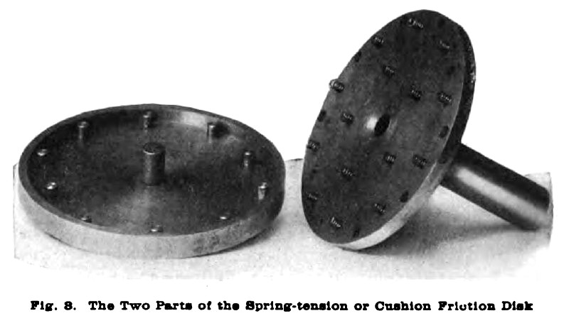
The latest design of friction-driven bench lathe built by the Cincinnati Precision Lathe Co., Cincinnati, Ohio, is shown by the front and rear views, Figs. 1 and 2. This lathe has an improved friction drive and a slide-rest screw-cutting attachment. The difference between the friction-driving mechanism of this lathe and those formerly built is in the control and the construction of the driven disk. The latter, instead of being a solid piece, is formed of two members which are separated by a series of coiled springs, thus forming a spring tension or "cushion" disk. These two parts are shown in detail in Fig. 3. In addition to springs, there are a number of steel guiding studs near the circumference of the disk and a large projecting hub in the center, all of which engage holes in the upper member. The guiding studs and hub are accurately fitted and there is also a bearing fit between the flange on the lower disk and the periphery of the upper disk, which insures a uniform tension at all points on the horizontal friction surface.
A further advantage claimed for this disk is that there is a very slight tendency of the horizontal friction plate to incline with relation to the driving shaft when the friction driving wheel is located outside of the center. This movement, while very slight, Is just sufficient to release that part of the friction filler material which would otherwise bear against the outer and more rapidly moving surfaces on the driven disk. In this way the sliding action between the two surfaces, which Is common to a rigid-disk friction drive, is obviated and the loss of friction material reduced. As the driving disk is applied on both sides of the driven disk center for obtaining forward and reverse speeds, the face or periphery of the driving disk wears uniformly or parallel to the friction driving shaft. As the driving disk approaches the center of the driven member, the spring tension increases slightly because the wheel comes directly under an increasing number of springs as it approaches the central and higher speed positions. In case a heavier spring tension is desired, the lower driving shaft can he raised by means of eccentric bushings provided.
With the horizontal friction disk as the driven member, if the lathe should be overloaded and the frictions caused to slip, the driving disk would continue to revolve and the wear would be uniform instead of forming flat spots. It is claimed that the location of the driving pulley at the base and the use of the cushioned disk reduces vibration to a minimum. The friction hand-control lever for varying the speeds has a circular inner end, which engages a recess or slot in the hub of the driving disk. The latter slides easily on the friction driving shaft and a longitudinal key inserted in the shaft, when the friction members are disengaged. The lower side of the control hand lever is so shaped as to readily drop into notches in the front gear cover, for retaining the friction driving wheel in any desired speed location on the driven disk.
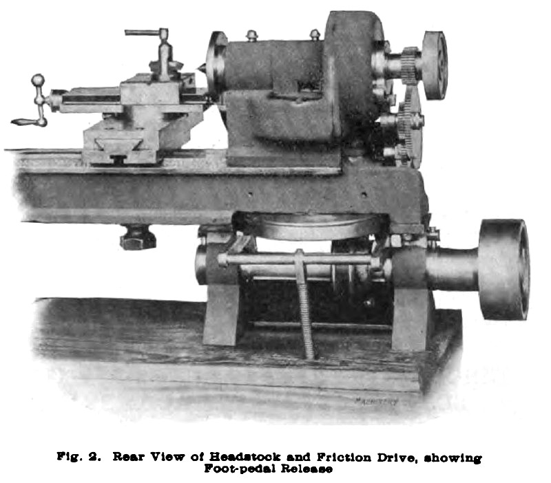
The rear view of the lathe head and friction drive shown in Fig. 2 illustrates the foot pedal release that is applied to this lathe. This releasing mechanism consists of two arms or levers, on the ends of which are bushed fiber rollers so arranged that when pressure is applied to the foot pedal the friction disk surface is raised, thereby disengaging the friction driving member. At the same time, the rollers act as a brake and stop the machine almost instantly. The forward or reverse speed changes can be quickly made, and, as the spindle can be stopped and started very quickly, threads can be cut close to a shoulder with safety. The spring seen between the bench and lever cross-arm Is for holding the lifting levers away from the disk when the lathe is in motion. The foot pedal is pushed under a retaining step on the floor when the lathe is to remain stationary. |
|
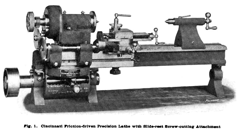 1912 Cincinnati Precision Lathe Co., Friction-Driven Swivel-Head Lathe with Screw Cutting Attachment
 1912 Cincinnati Precision Lathe Co., Friction-Driven Swivel-Head Lathe (Rear View)
 1912 Cincinnati Precision Lathe Co., Friction-Driven Swivel-Head Lathe (Cushion Friction Disc)
|
|