|
Title: |
1893 Article-Geiser Mfg. Co., Steam Traction Engine (Part 1) |
|
Source: |
The Engineer Magazine, 01 Sept 1893 pgs. 211-212 |
|
Insert Date: |
1/2/2015 2:17:25 PM |
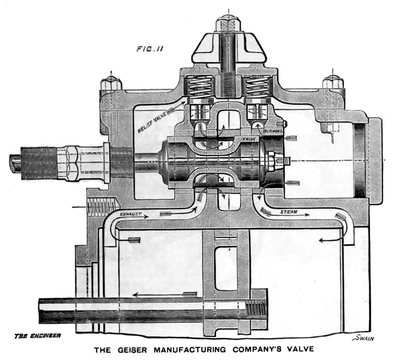
The traction engine exhibited by the Geiser Manufacturing Company, of Waynesboro, Pa.., offers many special features, and is shown in side elevation in Figs. 8 and 9. The boiler, Fig. 10, has a water-lined smoke-box, and is fitted with a chamber K in the steam space, which is in communication with the steam at the back end of the boiler, and which, by occupying space that the water would otherwise occupy when going down hill, keeps the crown sheet of the fire-box covered. The drawing shows the water line Z at a certain inclination and the water line V, which would be maintained with the same height of water if the chamber K were removed. The crown sheet slopes backward, and is stayed to the external shell. The valve is a piston valve illustrated in Fig. 11, and admits steam by its outside edges. It is driven by a single eccentric, with a reversing gear somewhat similar to that described in the last engine. This is shown in section and end elevation in Figs. 12 and 13. The crank shaft is hollow and has within it a rod, which can be moved forwards or backwards. This rod has attached to its outer end two pieces with diagonally grooved faces, between which fits a plate with similarly grooved faces forming part of the eccentric. By moving the rod forward or backward, this plate, and consequently the eccentric, is moved one or other way across the crank shaft. The traction wheels have cast iron hubs, wrought iron rims, and wooden spokes inserted in cups in the rim. The spokes are secured to the hubs by means of a plate bolted to its side, and can be tightened by means of bolts in the hub, which acting on a cone ring bearing against the ends of the spokes, fixes them into the rim.
The compensating gear is mounted on the main axle and is shown in Fig. 14. It is somewhat complicated by the arrangement for permitting motion of the driving shaft relatively to the boiler, so as always to keep the boiler level, as seen in Fig. 15. The driving pinion A gears with the large spur wheel B, whose axle is fixed on the engine frame, on a large hollow pin or trunnion. The motion of the wheel B is communicated through links C to a gimbel ring D, and thence by other links or rods E—which are fitted with springs to take up sudden shocks—to the wheel F in the compensating gear. The two sets of links by being attaches at right angles to one another, as seen in Fig. 16, form a coupling which permits the engine and the spur wheel B to get their centres out of line without interfering with the working of the gearing. The joints being knuckle joints, the first set because the links C are open-slotted and rounded on the inside at the ends, and the second set, namely, those of links D, because of the spring connection, the spur wheel B can deviate irregularly from the shaft to a sufficient extent, the extreme angle of heel never being great. The wheel F is attached to the internal spur wheel I seen in Fig. 14. This wheel is keyed on the main axle K, and forms part of the compensating gear. It engages through the pinions G and H with the internal spur wheel J. This latter is cast along with the hub of that driver which is loose on the shaft. The action of the compensating gear is precisely similar to that of the one previously described.
Images courtesy of Grace's Guide:
http://www.gracesguide.co.uk/images/4/4a/Er18930901.pdf |
|
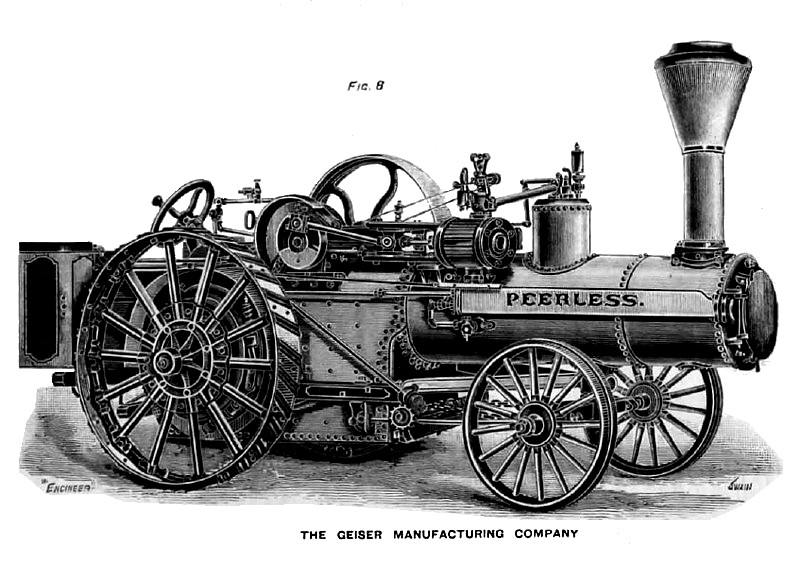 1893 Geiser Mfg. Co., Steam Traction Engine (Right Side)
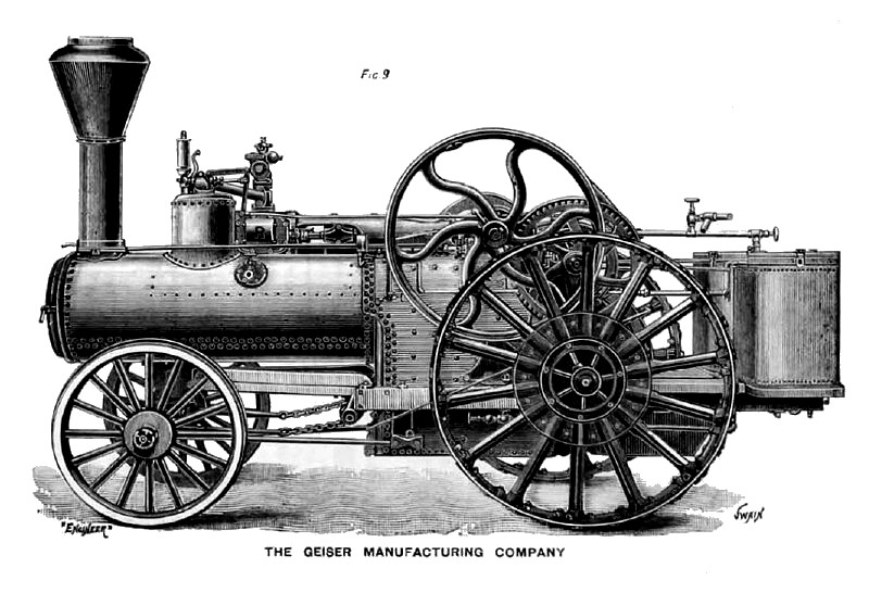 1893 Geiser Mfg. Co., Steam Traction Engine (Left Side)
 1893 Geiser Mfg. Co., Steam Traction Engine (Steam Valve)
|
|