|
Title: |
1893 Article-A. W. Stevens & Son, Steam Traction Engine (Part 3) |
|
Source: |
The Engineer Magazine, 01 Sept 1893 pgs. 210-211 |
|
Insert Date: |
12/31/2014 5:27:21 PM |
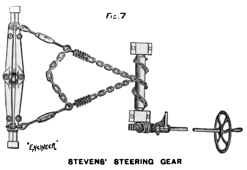
The steering gear is shown in Fig. 7, and will be readily understood in conjunction with Figs. 1 and 2. The cross chain connecting the steering chains becomes taut before the axle has turned through such an angle that the wheel can strike the boiler, and prevents further motion in that direction. The brake consists of a steel band going over a flanged pulley on the countershaft, and is applied by means of a foot lever. The friction clutch is shown in Fig. 3,and consists of a spider having an extended hub that encircles a sleeve on the crank shaft, and to the end of which is secured the driving pinion. Attached to the spider are two shoe-holders pivoted at one end and connected to toggle joint arms at the other end. The arms at their base are joined to a collar that slides upon the spider hub. When the clutch is not in action the spider hub rides loosely on the revolving crankshaft sleeve. By means of a bell-crank lever the sliding collar can be driven towards the spider, forcing the wooden shoes out against the inner rim of the ?y-wheel and engaging them thereto, thus transmitting power to the driving pinion.
Images courtesy of Grace's Guide:
http://www.gracesguide.co.uk/images/4/4a/Er18930901.pdf |
|
 1893 A. W. Stevens & Son, Steam Traction Engine (Steering Gear)
|
|