|
Title: |
1893 Article-A. W. Stevens & Son, Steam Traction Engine (Part 2) |
|
Source: |
The Engineer Magazine, 01 Sept 1893 pgs. 210-211 |
|
Insert Date: |
12/31/2014 5:28:58 PM |
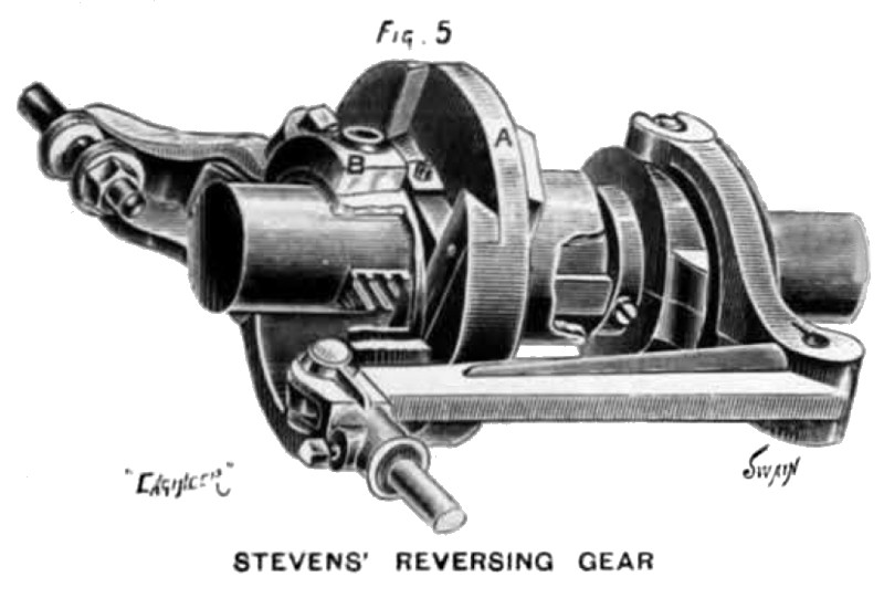
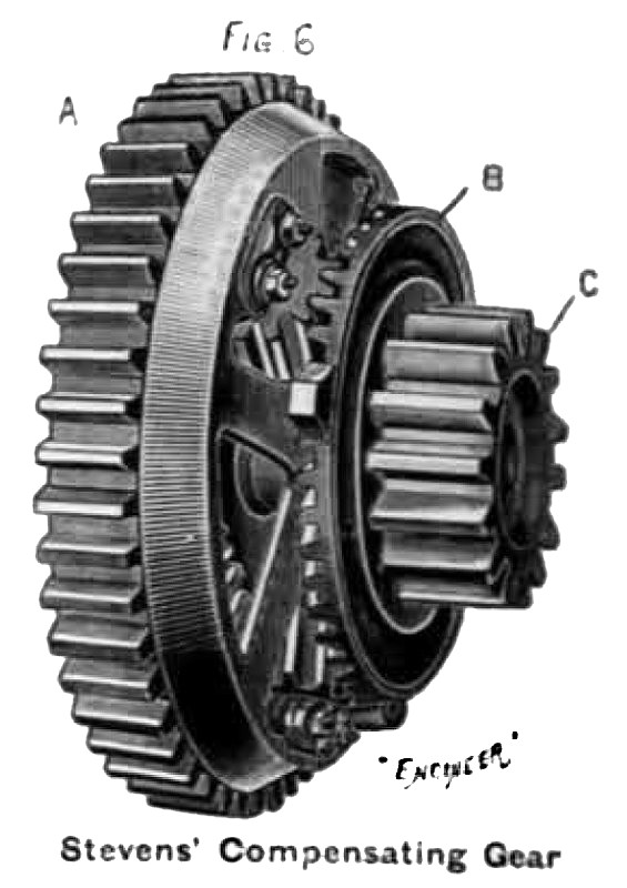
An engine, which may be considered as typical, is that exhibited by A. W. Stevens and Sons, Auburn, New York. Views of this engine are given in Figs. 1,2, and 3. The boiler is of the wagon-top locomotive type, and is shown in section in Fig. 4. The barrel is 26 in. in diameter, and contains 42 flues, 2 in. in diameter, 60 in. long, and placed in vertical rows with 2¾ in. spacing between centres. The tube plates have the holes drilled. The fire-box is of steel, 33 in. long, 24in, wide, and 30in. high, and is intended for coal. The crown sheet slopes backward and is stayed to the external shell. The entire engine frame consisting of saddles, brackets, cylinder, steam chest, guides, and both crank shaft bearings, is cast in one piece and placed on the top of the boiler. In the 12-horse power engine exhibited, the cylinder is 7½ in. by 10½ in., and has its back cover cast with it. The connecting-rod is of steel, three times the length of the stroke, and has strap ends. The crank in is 2½ in. in diameter, forced into the crank by hydraulic pressure. The crank shaft bearings are 8 in. long, and are set at an angle of 45 deg. The valve is a simple slide valve driven by a single eccentric. The device for varying the cut-off and reversing is shown in Fig. 5, which is a perspective view with part of the eccentric broken out. An eccentric disc, A, revolves with the shaft. Across its face is cut a broad seat with bevel sides, into which slides a steel plate spanning the shaft. To the side of this plate the eccentric B in fastened. Within the opening of the slides are cut diagonal grooves, into which gears a steel rack that is moved forwards and backwards by a bell crank. This operation causes the eccentric to move across the shaft. The driving wheels are 60 in. in diameter, 11in. face; they are solid, with wrought iron spokes cast into the hubs and rims. The cleats on the rim extend half way, and square across from either edge alternately. The front wheels are 40 in. in diameter, 7 in. face, and have a rib encircling the centre of the rim to prevent side slipping The crank shaft has at one end a fly-wheel and a small spur wheel. This latter gears with a large one, which in turn engages with the wheel A— Fig. 6— of the compensating gear.
The wheel A is keyed to the countershaft, and has a bevel wheel cast in its interior, and this faces a similar bevel wheel B on the same shaft, and is connected to it through three loose bevel pinions. The spur wheel C is cast in one with the bevel wheel B, and runs loose on the countershaft. C is at the end of the countershaft, and gears with a spur wheel— seen in Fig. 1— on the driver at its side, this driver being loose on the shaft. At the other end of the countershaft is a pinion similar to C, but fixed to the shaft, and gearing with the driver on that side which is also keyed to its shaft. The action of the compensating gear can now be readily seen. When the engine is moving along a straight path, the whole gear rotates as one piece; but when one wheel encounters a greater resistance than the other, as in turning round curves, the bevel pinions rotate in such direction as to make the rate of revolution less on that aide on which the greater resistance is.
Images courtesy of Grace's Guide:
http://www.gracesguide.co.uk/images/4/4a/Er18930901.pdf |
|
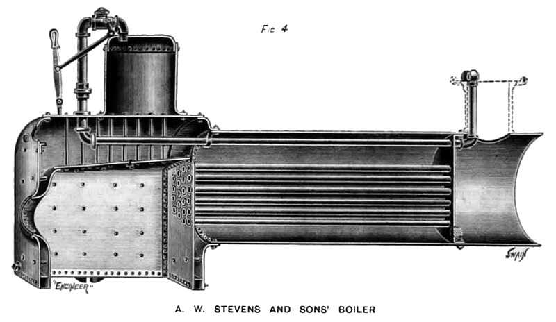 1893 A. W. Stevens & Son, Steam Traction Engine (Boiler)
 1893 A. W. Stevens & Son, Steam Traction Engine (Reversing Gear)
 1893 A. W. Stevens & Son, Steam Traction Engine (Compensating Gear)
|
|