|
Title: |
1893 Article-Westinghouse Machine Co., 250 H. P. Steam Engine |
|
Source: |
The Engineer Magazine, 01 Sept 1893 pgs. 207-208 |
|
Insert Date: |
12/30/2014 7:23:54 PM |
The Westinghouse exhibit of steam engines is of high importance, not only on account of its large size and power, but also, and chie?y, because of the independent originality of the designs and the thorough-going carefulness, mechanical skill and ingenuity shown, both in the general arrangements and principles, and in the constructive details. These designs are due to Mr. F. M. Rites, the chief mechanical engineer of the Westinghouse Machine Company, of Pittsburgh; and it is to Mr. Rites’ intelligent explanation that I am indebted for much of what follows. It may be useful to mention that the three firms of Westinghouse, Church, Kerr and Co., of New York, the Westinghouse Machine Company, and the Westinghouse Electric Manufacturing Company, both of Pittsburgh, but in different parts of the city, are all commercially and financially distinct, and under different technical management; the main connecting link between them being the fact that Mr. George Westinghouse is the chief active director in each concern.
The engines are all of the inverted vertical type, and they are all coupled direct to the dynamos which they drive. These dynamos have already been described in detail in THE ENGINEER. The direct coupling between high-speed engine and dynamo is quite a new thing in America. This Westinghouse exhibit is the only American example at the Chicago Exhibition. In the Weston electric lighting installation at the Brooklyn Bridge, N.Y., which was recently referred to, and which has only been recently completed, there are two multiplications of speed by means of three belts and two counter-shafts, between each engine and the dynamos it drives. The Westinghouse Machine Company couples the engine and dynamo shaft together by means of an intermediate cast iron disc lying between the two coupling flanges, as seen in Fig. 1, and two pairs of links. The first pair, between engine and intermediate disc, lie parallel to each other on opposite sides of the shaft, and, of course, pull in opposite directions. The second pair, also parallel to each other, lie at right angles to the first pair. The result is that the two shafts do not need to lie exactly in line. For the 1,200 indicated horse-power engine the intermediate disc is 3 in. thick, and the link pins are of
steel, and have 4½ in. diameter at their bearing, being shouldered down to 4 in. in the flanges and disc.
The total exhibit consists of :—
Six compound engines each of 1200 I.H.P.
Two compound engines each of 330 I.H.P.
Three compound engines each of 125 I.H.P.
Two simple engines each of 150 I.H.P.
One compound engine of 250 I.H.P.
Total indicated horse-power 8,785
The brake horse-power of the large engines is 1,000 each. These are steeple or tandem engines, with the large cylinder above the small one. The longitudinal and cross sections are shown in Fig. 1. The cylinders are 21½ in. and 37 in. diameter, by 22 in. stroke, and run at 200 revolutions per minute, giving a piston speed of 730 ft. per minute. Neither cylinder is jacketed. The latest cut-off in high-pressure cylinder is three-fourths. and with the normal cut-off of under three-eighths the total grade of expansion is about six. The piston packing consists of plain cast iron rings sprung into different grooves. The piston, connecting, eccentric, and valve rods, and the shaft are all of forged steel, and the cranks are of cast steel. The crank-pin bearing is 11in. diameter and 12 in. long, is of gun-metal, and has its whole surface babbited. The “wrist-pin," or crosshead pin, is 6 in. diameter by 12 in. long. The eccentrics have 25 in. diameter by 5 in. bearing width, and are of cast iron, the strap being malleable cast iron and babbited. The crank discs are loaded so as to balance rather less than two-thirds of the reciprocating weight. The frame from the lower cover of the
high-pressure cylinder to the base-plate is boxed in, and the "crank case" thus formed is filled with water with a layer of oil floating on its surface up to within a minute distance of the lower edge of the crank shaft. Inside this case lie the crank discs, the low-pressure eccentric, and the inner part of the high-pressure valve gear. The low-pressure eccentric drives a guided crosshead, from which ascend two valve rods laying hold of the heavy low-pressure D-slide at its two sides. This arrangement is required because of the high-pressure cylinder being below the other, so that the low-pressure valve rod has to be split in order to pass the high-pressure gear. This low-pressure valve rod guide block or crosshead, the main crosshead, and the internal portion of the high-pressure valve gear, are all lubricated by the oily spray dashed up by the cranks. The lubricant is all fed in through the main crank shaft bearings, any that escapes by than outside edges of these bearings being caught and returned to the crank case by a chamber or passage cast in. The lubricant used is a. thick heavy black cheap West Virginia oil, made by J. Dalzell, of Pittsburgh. The crank shaft. bearings are babbited, and are 14 in. diameter by 30 in. long. The piston and valves are lubricated by oil introduced into the steam pipe as usual.
The governor is a wheel governor of the general type now mostly used by American engineers, the specialty being that the wheel is boxed in, completely enclosing all the governor parts, and the case so formed is filled up with oil. Figs. 2 and 3 show this governor, Fig. 2 with the balls resting against the inner stop, giving the latest cut-of, namely three-quarters, which position is maintained until the speed rises close to the normal speed of 200, when it is rapidly changed to that shown in Fig. 3, where the weights B B are pressing against the stop-pins s s, seen Fig. 2.
The weights are pivoted about the pins b b fixed in the wheel, and they are linked together by the rod e, to insure that both ?y out and in together. They are drawn in by two springs D D made of 7/8 in. round wire, with nineteen coils on a mandrel 2½ in. diameter. One weight only is linked by the rod f to the eccentric, and shifts it round the centre d across the crank shaft S, the pin d being set in the wheel, which is keyed to the shaft. The eccentric C and its tailpiece c are outside the wheel case, while the other parts shown here are inside the same case, so that the link f does not lay hold of the eccentric directly, as would appear from the diagram, but by means of a lever inside the case and keyed to pin d; while outside, again, the tailpiece c is also keyed to the same pin d. It is thus apparent that there must be a heavy strain on this pin, and on its two keys; not only when shifting the eccentric, but also in steady running, which, however, is greatly less than it would he were it not for the balance of the inertia of the reciprocating masses by the air cushions. This pin is of steel , is 3½ in. diameter, and its bearing in the boss cast for it on the wheel is 16½ in. long. This bearing is kept sufficiently lubricated by the oil in the wheel case. The position of the centre d is very carefully chosen, so that the lead increases very slightly while shifting from latest to normal cut-off and then decreases gradually to zero for cut-off at the beginning of the stroke.
The action of the oil filling up the governor wheel case is interesting. It, of course, decreases the virtual weight of the bells by the flotation value or weight of the displaced oil; but this has no influence on the action of the governor, which depends in no degree upon weight. In fact, the two weights B B always balance each other through the link e. The centrifugal force of the oil, however, counteracts partially that of the weight by creating a. greater fluid pressure in the outer portions of the case than in the inner portions, which difference of fluid pressures gives a fluid radial inward or centripetal force on the balls helping the centripetal force of the springs. The amount of this action is exactly the same as if the mass of the ball were diminished in the same proportion as its weight is actually decreased. In this particular governor running at 200 revolutions the effect as to make the balls more outwards at a speed fifteen revolutions faster than that at which they would move if there were no oil in the case. But the oil has a second influence no less interesting. When the speed of revolution of the shaft and wheel increases, the oil lags behind and presses on the weights B B, so as to tend to cause them to lag behind also. Such a retardatory motion of the weights corresponds with an outward radial motion on their part, and thus this action of the oil, although not very energetic on account of the fluidity of the material, increases the sensitiveness of the governor. The eccentric rod drives a duplex lever on a rocking shaft. The one lever to which the rod is directly pinned is loose upon the shaft, and can be drawn an inch or so radially inwards towards the shaft by a screw and hand wheel. It has its end pointed in the form of a blunted knife edge. This point enters a corresponding recess in the other lever when the screw pushes it outwards. By this means the eccentric is thrown in or out of gear with the rocking shaft and valve rod. From the end of the keyed lever passes a pin 3 in. diameter and 7 in. long inwards to the inside space in the main frame or crank-case. The other end of this pin is carried by an equal inside lever also keyed on the rocking shaft. By means of a suitable block this long pin drives up and down a plunger piston in a vertical cylinder clearly seen in Fig. 1. This works in a cylinder closed at both ends and having these ends filled with air This air cushions the momentum of the valve gear and valve at each end of the stroke, the acceleration of momentum required at each end being so considerable that wear on the driving joints would rapidly accumulate if it were not for these air cushions. This subsidiary cylinder also serves a second purpose, namely, as a steam relay when starting the engine, to
move the valve up and down without its being in gear with the eccentric. By a conveniently placed small three-way cock, the driver admits steam alternately above and below the plunger piston, thus throwing the valve over and moving the engine round until all parts are thoroughly freed from water, when he puts the eccentric in gear by the means already described. The high-pressure valve is of the piston type, 18 in. in diameter, and is packed by simple cast iron rings. The steam ports are made specially ample, the high-pressure ports being 8½ in. wide, while the low-pressure steam ports are 3½ in. wide. The steam admission to the high-pressure cylinder is through the central annular space surrounding the piston valve, which, therefore cuts of by its inside edges. The internal volume of the piston valve, along with that of the low-pressure valve chest, form an intermediate receiver of no inconsiderable size. The engine runs with remarkable quietness and steadiness. Its ?y-wheel is 11 ft. in diameter and weighs 12 tons. It is connected to a surface condenser made by a distinct firm, and forming a distinct exhibit. Its steam pipe is 10 in. and exhaust 14 in. in diameter.
The 330 indicated horse-power and 125 indicated horse-power are both of the type shown in Fig. 4. The larger has cylinders 18 in. and 30 in. diameter by 16 in. stroke, and runs at 250 revolutions; the smaller has 12 in. and 20 in. cylinders by 12 in. stroke, and runs at 300 revolutions per minute. They are compound engines, single-acting in each cylinder, so as to maintain constancy in direction of bearing pressure at the high speeds used. They also are condensing, and have the same style of governor as already described for the large engine. In this case, however, the eccentric and its strap have their bearing surfaces turned spherical, so as to form a ball joint, permitting the upper end of the eccentric rod to drive also by a ball joint the end of a bell crank whose other arm is linked to the horizontal valve rod. There is one valve only for the two cylinders; it is a piston valve, and it and its case are placed horizontally across the top of the two cylinders. There being no intermediate receiver, the cranks are placed opposite and the two sets of reciprocating parts are made of the same weight, so as to balance. The steam is admitted to the high-pressure cylinder through the central recess in the valve, which later on forms the passage from high-pressure to low-pressure cylinder. Only three edges of the valve are effective in governing the steam distribution, the edge furthest from the bell crank never passing the steam inlet, and the end space in the valve-chest beyond this edge being filled with exhaust steam to balance the exhaust pressure at the other end of the valve. Fig. 4 is clear enough to obviate the need of further description of this valve gear. It appears to give an excellent series of indicator cards under varied loads, this being due to skilful designing of the taps and careful setting of the eccentric and governor. In comparing the use of the three edges only of this valve with that of the four edges of an ordinary slide, as used in a double-acting cylinder, it must be remembered that there are in the latter case eight points of distribution to be determined, viz., admission, cut-off, exhaust, and compression at each end of cylinder, while to determine these there are only five elements of design, namely, the four laps on the valve and the angular advance of the eccentric. In the present engine there are also eight points of distribution for the two cylinders, but the admission and the exhaust need not be different in the two cylinders. In these engines the two cranks and their pins are all east in one piece in steel, the straight portions of the shaft being forged steel, and being keyed into the outside crank discs.
Images courtesy of Grace's Guide:
http://www.gracesguide.co.uk/images/4/4a/Er18930901.pdf |
|
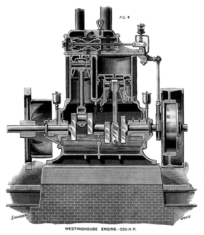 1893 Westinghouse Machine Co., 250 H. P. Steam Engine
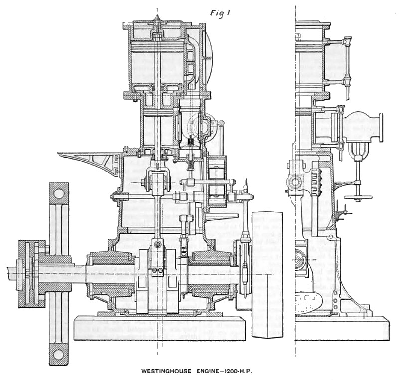 1893 Westinghouse Machine Co., 1,200 H. P. Steam Engine (Sectional View)
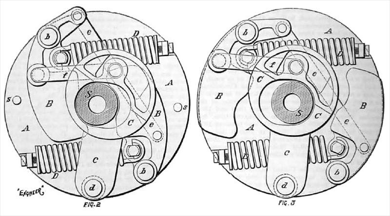 1893 Westinghouse Machine Co., 250 H. P. Steam Engine Governors (Sectional View)
|
|