|
Title: |
1860 Article-Stover Machine Co., Combination Planer |
|
Source: |
Scientific American, V 3 #24, 08 Dec 1860, pgs. 369 |
|
Insert Date: |
12/23/2014 9:46:46 PM |
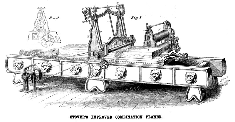
The accompanying engraving represents the Stover Machine Company’s combination planer, the several peculiarities of which were invented by H. D. Stover, of this city, and secured by Letters Patent issued May 19, 1857. Aug. 21, 1860, and Sept. 14, 1860.
The cut shows the machine as arranged for doing the work of a Daniels’ planer, planing straight and out of wind, and squaring up and surfacing heavy and dimension timber or boards.
The stuff, A, is held firmly to the platen, B, while being passed under the cutting cylinder by the dogs, D and E. The dog, E, is moved from end to end of the platen, B, simply by raising the back end out of the notch in the rack, O. The dog, D, is fixed to the platen by means of pins, 14, placed in the sides of the platen, and the apparatus that carries the dogging bars is so arranged with adjustable and variable inclined planes pressing against the pins, a, so that any desired pressure may be attained, both to press the dogs forward into the stuff, and to hold them down securely to the platen by turning the hand wheel attached to the screw. The rack, O, is made with mouthpieces, so as to prevent chips lodging therein. The platen is constructed of iron below, with a top of wood, and, when so ordered, made in two parts, with a ball between, so as to tip universally and be secured to plane stuff either beveled or level and parallel in thickness. The platen is moved on ways constructed with an adjustable gib rest, which can be taken up, and which also allows of the frame being constructed much shorter than formerly, as it is impossible for the platen to tip up in end. The platen is moved back and forward under the cutting cylinders by means of a friction feed, and so arranged as to run back twice as fast as forward, being moved either way by simply turning the hand wheel, Q, to the right or left, as the case may be. This is a great advantage, as the jar of starting a heavy piece of work suddenly is wholly obviated, and the platen can be reversed much sooner than formerly, and it is impossible to strip any teeth—a difficulty often encountered before. The platen is also constructed to run on rollers when carrying heavy loads, thus diminishing the power used to overcome the friction of the parts; these rollers being thrown into use or out in a moment. ‘The cutting cylinder, C, is furnished with flat cutters, beveled on their outer surface and parallel to the axis of the cutter head, C ; the cutting edges being in the surface of a cylinder whose axis is coincident with the axis of motion, so as to impart a drawing stroke, the drawing stroke being well known among all workers of wood to be the only stroke that easily removes the chip and leaves a smooth surface. The cutting cylinder, mode of the best wrought iron with steel bearings, is also so formed as to make a heel or cap iron for the cutting knife, being adjustable, like a hand plane, for the purpose of cutting fine or heavy, in either hard, soft, straight or crooked grain wood, as the case may be. The heel iron formed on the cutting cylinder is so constructed as to break the chip and cause it to be thrown from the cutting cylinder as soon as cut, thus making the action of the cutting cylinder perfectly free by the action of the recesses and pressure edge. The cutting cylinder is raised by means of a screw attached to each end of its crosshead, thus securing it exactly parallel with the face of the platen, either in its elevation or depression. The cutting cylinder is run in long boxes at each end, said boxes being lined with Babbitt metal, and supplied with a new and superior arrangement for oiling the bearings so they can never heat. The crosshead, R, is secured to the upright posts, H, by means of a gib rest, and can be adjusted very readily, thus preventing any side motions or in security, and doing away with the hook bolts formerly used. The screws for raising the crosshead are encased in pocket, S, cast on the upright frame, H, and thus securely kept free from shavings and dirt, whereby they last much longer. At T T T are the bevel wheels for communicating the motion from the handle to the horizontal shaft, and thence to the screws; these bevel wheels being encased in an ornamental shell of iron, and secured free from the annoyance of dirt and shavings, being free to work at all times without cleaning the shavings from them. The raising screws run in the crosshead and tie at the top of frames in nuts constructed with a rolling fit in a loose pocket, for the purpose of always being in line without binding, and still perfectly secure and without play when at work. The crosshead is arched in the center, thus admitting of the free exit of shavings, and when so desired, a tube is constructed to carry the shavings to the fire room of the mill without the exertion of any extra amount of power or any complication of parts.
At the back of the crosshead, R, is a frame secured, and to it are attached an adjustable pressure roll, wiper and gage. The pressure roll can never mar the board by pressing shavings into its surface, as the wiper effectually cleans the surface of the lumber before it comes in contact with the roll, and there is also a steel scraper in contact with the roll to clean it of any pitchy or glutinous substance which may attach to it, and which, if not removed, would soon press into the lumber and deface it after being planed. In combination with the roll is also a gage, used mostly for soft and very thin work, as it comes closer under the cutting cylinder, and by the turning of two thumbscrews, either the gage or the roll may be thrown down, and in use depending upon the kind of lumber to be planed.
In front of the cutting cylinder is seen the front pressure roll, U, and its boxes, V V. The boxes are so constructed as to carry the pressure within them precisely as set, and under any elevation of feed; they are readily adjusted to carry any pressure desired. The advantages of this arrangement are very obvious as every practical man has seen the great disadvantage of planing a piece thin at one end and thick at the other. At the thin end, when the work of cutting the chip was comparatively small, the spring exerted little or no force, for it was extended nearly in its natural position; but when the heavy chip came to be taken off, and the power of the machine was being exerted for that purpose, there was also required an extra power to run the stuff under the pressure roll in consequence of the force exerted by the spring in its much contracted and depressed state. Another great advantage is seen in this arrangement when changing from dry seasoned to wet and sappy lumber, as the increased pressure upon the rolls on the last named lumber can very readily be obtained.
At W is seen the gage attached to the crosshead, R, and running through an eye in the tie between the side frames at the top. This gage serves it double purpose. On its front surface are marked inches and fractional parts, indicating, by reference to X, the thickness of lumber being Planed upon the platen. At X is a thumb screw which, being set hard down, holds the gage, and thereby the crosshead and cutting cylinder form any movement, either by jar or otherwise and securing a perfectly parallel thickness throughout the piece being planed. At N, Fig. 2, are seen the feed rolls, or Woodworth attachment for surface planing only and such work as was formerly done on me Woodworth Planers. This apparatus consists of two frames for supporting the work into which are placed the boxes and the rolls, YY. The bottom roll is smooth and adjusted in height by set screws secured in the bottom of the frame and supporting its journal boxes, elevating the roll exactly to the proper position for passing the boards (or plank) under the cutting cylinder. The upper roll is creased so as to adhere to the lumber being worked, to secure its proper passage along under the cutting cylinder. At each end it is secured by and revolves in boxes of the same construction as the front pressure roll boxes, carrying its pressure always the same, however varying in thickness the piece being planed may be, supplying the place of weights and levers formerly used, and overcoming the objections formerly urged to the use of rubber springs, which always held the same pressure when planing a thick or thin piece. The upper roll is elevated and let down by a handle, bevel wheels and screw similar to
those used for raising and lowering the cutting cylinder crosshead.
The rolls are moved by an independent feed arrangement from the shaft which runs the cutting cylinder, and they are connected at the end and are always in gear with each other, by means of an ingenious combination of radiating arms and gear wheels, running easily and very strongly, and so constructed as to be free from shavings. The feed rolls are shown as out of gear when not required, they are slid out of gear by simply pushing the frames in end on a frame provided for that purpose and when wanted, the platen is run out of gear, and the feed rolls are pushed in place, running into gear, and securing themselves perfectly solid, as if constructed in the place; the time required to shift from planing straight and out of wind to that of surfacing being merely nothing. The sides of the machine are constructed of iron, with the legs cast on them, thus making a very secure framework. At Z are seen match are seen matching heads for matching the boards before they are run under the cutting cylinder, which are so arranged as to automatically find and correctly match the entire length of the edge of a board. To the feed rolls is also attached a mouth piece for entering boards with much expedition and certainty of action. The machine is got up in a very thorough manner, wholly of iron and tastefully ornamented, the castings being of a new and beautiful design.
The office of the Stover Machine Company is located at Nos. 11 and 13 Platt Street, this City, to which place persons desiring further information should apply.
U. S. Patent #'s 14,421; 29,727 & 29,923. |
|
 1860 Stover Machine Co., Combination Planer
|
|