|
Title: |
1860 Article-Miller & Dennison, Feloe Rounding Machine |
|
Source: |
Scientific American, V 3 #23, 01 Dec 1860, pgs. 353 |
|
Insert Date: |
12/23/2014 9:48:28 PM |
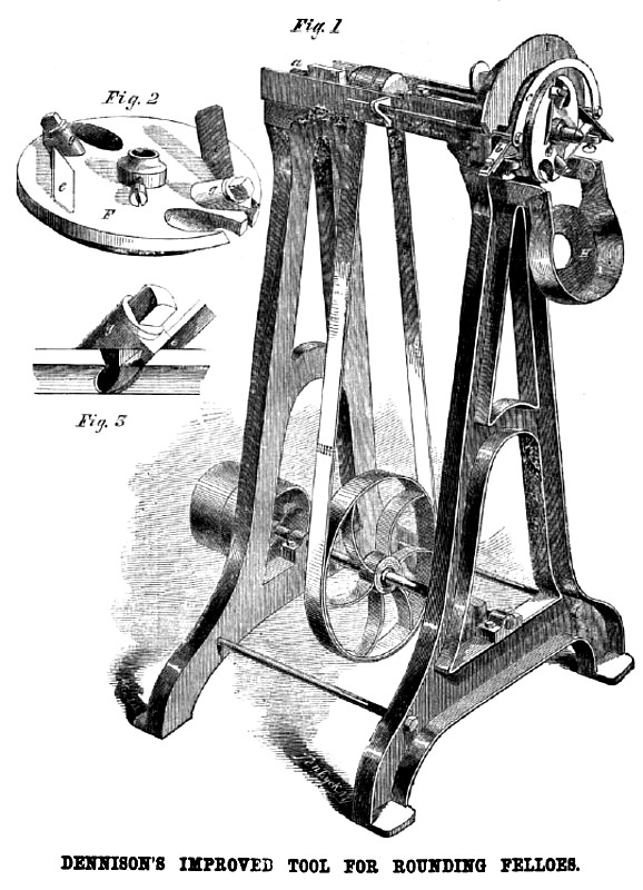
One after another, the several hand processes of working wood are passed over to the operation of machinery. The neat little tool represented in the accompanying engravings is designed for taking off the corners and finishing the inner curve of the felloes of carriage wheels. This operation has been heretofore performed by hand, and it has taken three-quarters of an hour to round the felloes for the four wheels of a carriage; but with the revolving cutters of this machine, running with a velocity of 4,000 revolutions per minute, a set of felloes can be rounded in four minutes,
The felloes are rounded after they are bent and bored for the spokes. There are two sets of cutters, one set for cutting off each of the corners, and each set is secured in a revolving disk, Fig. 2, which disks have their inner edges hollowed, so as to form a semicircular groove in their common periphery when they are placed on their shaft, a, Fig. 1. Between the two disks is a thin, stationary plate, operating as a guide or rest for the felloe, to prevent it from being cut away more than is required. Pressing upon the periphery of the rest is a plate, b, which has an upright stud or pin, c, upon its end, for regulating the distance from the spoke at which the cutting of the corners shall begin, the portion of the felloe about each spoke being left square. The operator lays the felloe with the inner side in the groove formed in the periphery of the two disks which constitute the cutter head, with the pin, e, in one of the spoke holes, and then turns it down into the groove till it bears upon the rest. As the cutters take hold, the operator feeds the felloe along, pushing it from him, till it is rounded quite half way to the succeeding spoke hole, when he raises the felloe and catches the next hole upon the pin, c, and thus proceeds till the whole of the stick is rounded upon one side of all the spoke holes, full half way to the succeeding holes, when the stick is reversed and the process repented, completing the operation. The plate, b, is made adjustable, to leave a longer or shorter portion of the felloe about the spokes square, as may be desired.
The mode of securing the knives to the disks is clearly shown in Figs. 2 and 3. The knives, : c a, made of flat pieces of cast steel, are passed through slits in the disk, F, and are held in place by the thick, metal tubes, G G which have notches in their lower sides to catch over the edges of the cutters, and are secured very firmly to the disks by screws which pass through them and enter the disks. From the oblique position of the tubes, G G, they cause the cutters to press against both the sides and the edges of the slits in the disks, and thus hold them very securely.
To secure the felloe directly in the middle of the groove in the cutter head, the plate, I, is placed for one side of the felloe to rest against, and the plate, J, is drawn by spiral springs against the opposite side of the felloe. The plate, I, is made adjustable in its position,
it was invented—the finishing of felloes of wheels.
This valuable implement was invented by C. H, Dennison, of Brattlcboro, Vt., and the first patent was granted, December 6th, 1859, to A. Miller, to whom the invention had been assigned. Application has, however, been made, through the Scientific American Patent Agency, for patents on improvements, all of which are embraced in the above description. Further information in relation to the matter may be obtained by addressing Asa Miller, or C. H. Dennison, at Brattleboro, Vermont.
US Patent: 26,392 |
|
 1860 Miller & Dennison, Feloe Rounding Machine
|
|