|
Title: |
1876 Article-Corliss Steam Engine Works, Gear Cutter (Part 1) |
|
Source: |
Scientific American, Supplement, V 2 #49, 02 Dec 1876, pgs. 783-788 |
|
Insert Date: |
12/17/2014 7:27:53 PM |
The cutting of bevel gear-wheels so that they shall have that exact symmetry and mathematical and mechanical perfection which are given to the spur gear-wheel, and which are indispensable to their perfect working is a problem which has been found, perhaps, more difficult of solution than any which has been presented to the mechanic. To cut perfectly a spur or similar gear, the mechanical problem has been, simply, to make a circular or disk milling cutter, having for a section of that part of it containing the cutting teeth the form required for the space to be out between two teeth of the given wheel; and a machine which would accurately divide the circle into the required number of parts, hold securely the wheel while being cut, and rotate and pass this milling cutter across the face of the wheel; such an apparatus, adjustable to the varying conditions as to dimensions of gear, number of teeth required etc" has long been in use, and the cutting of spur gearing has for many years been easily, perfectly, and cheaply done.
To cut a bevel gear, however, requires the application of entirely different principles and mechanism. Previous to the invention by Mr. George H. Corliss of a machine for this purpose, patented in 1849, and at that time illustrated in Appleton’s “ Dictionary of Mechanics," and almost universally since by others, the method of preparing a bevel-wheel within reasonable accuracy has been, to place the cast blank or wheel in the ordinary gear-cutting machine, such as is constructed to permit of the cutting being done at different angles with the axis of the gear to be cut, and to pass through twice on a line corresponding to the bottom of the s ace between teeth and one side of the bottom of the flank of the tooth, a revolving milling cutter, having such a form of section through the cutting part as corresponds to the correct form of the larger end of the tooth, but of such thickness as to preserve all the metal necessary to the perfection of the small end of the tooth by subsequent operations, afterwards dressing down by hand work the small ends of the teeth to their proper shape, and then in the same way the whole body of the tooth; the only part of the new tooth, when finished, receiving a correct form from the cutter being the large extremity. The small ends of the teeth are sometimes given the proper form by using a second cutter having the exact outline of that part of the tooth and entering it from the smaller towards the larger end a sufficient distance only to impart the proper form to it, then dressing by straightedge, chisel and file, the body of the tooth between these extreme points to correspond; but at best this is no more correct than handwork can make it, and is most laborious and expensive.
It is impossible to cut a bevel gear correct with a revolving cutter, whether it be the disk form whose axis is in position of a tangent to the periphery of the wheel to be cut or nearly so, or that kind which is sometimes used for the cutting of very large spur gearing, which is carried upon the end of a spindle whose axis occupies nearly the position of a radius of the wheel. Let the controlling mechanism be what it may, neither of these nor any revolving toothed cutter can finish the tooth of a bevel wheel correctly, unless such cutter could be made to be capable of a uniform contraction or expansion in every dimension as it was passed through.
A tooth or space between two teeth in a bevel wheel is a symmetrically reduced form, from the largest to the smallest end of the tooth or space, and any straight line drawn upon them and touching homologous points throughout the length of the tooth, it produced towards the smaller diameter of the wheel, will intersect at a common point, and that is identical with the point at which the axes of any pair of bevel wheels intersect. The only way then in which a wheel of this kind can be correctly cut is, by the use of a cutter which will operate practically upon a line, as is the case, for instance, with the ordinary “diamond point" lathe tool; and it must be actuated by mechanism such that the lines upon which it moves when cutting must be those which converge to the common point of intersection. This applies of course only to the finishing of wheels which have been cast in the rough, leaving an sufficient material in the teeth to finish. If the given wheel is cast solid, it may be put in the ordinary cutting engine, and with a disk or rotating cutter having parallel sides, parallel grooves may be cut, not exceeding in width the smallest part of the small end of the space to be left between the finished teeth, and then finished in the machine under consideration; or the same preparatory work may be done on such a wheel in the Corliss machine, although, perhaps, not quite so cheaply.
To dress up accurately the face and flank of the tooth of a bevel gear w eel and the bottom of the intervening space with a tool, the cutting point of which should reciprocate practically upon the converging lines of a mathematically correct wheel, and tracing on the finished surface such narrow lines as are left by the planer tool with a comparatively fine feed, is the problem, t e solution of which has been essayed by Mr. Corliss, and the first prerequisite was to make that part of the machine which carried the tool reciprocate on slides which, while they permitted of the cutting point of the tool always following the converging lines, should be capable of motion in all directions upon the point of convergence as a centre; and the problem was the more difficult from the fact that, in order to produce the mathematically correct wheel, no part of the machine itself could occupy or be allowed to move on the convergent lines, as the cutting point of the tool could only be permitted to follow them.
As stated above, this was practically done by Mr. Corliss in 1849, and a machine which was the parent of the one under consideration has been in use by him since that time. It was not, however, of such proportions as to be capable of cutting the large bevels to be used on the Centennial shafting; and a more complete and elegant solution of the problem is to be found in the present machine.
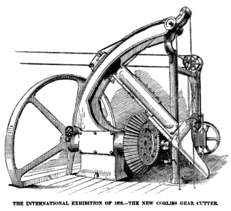
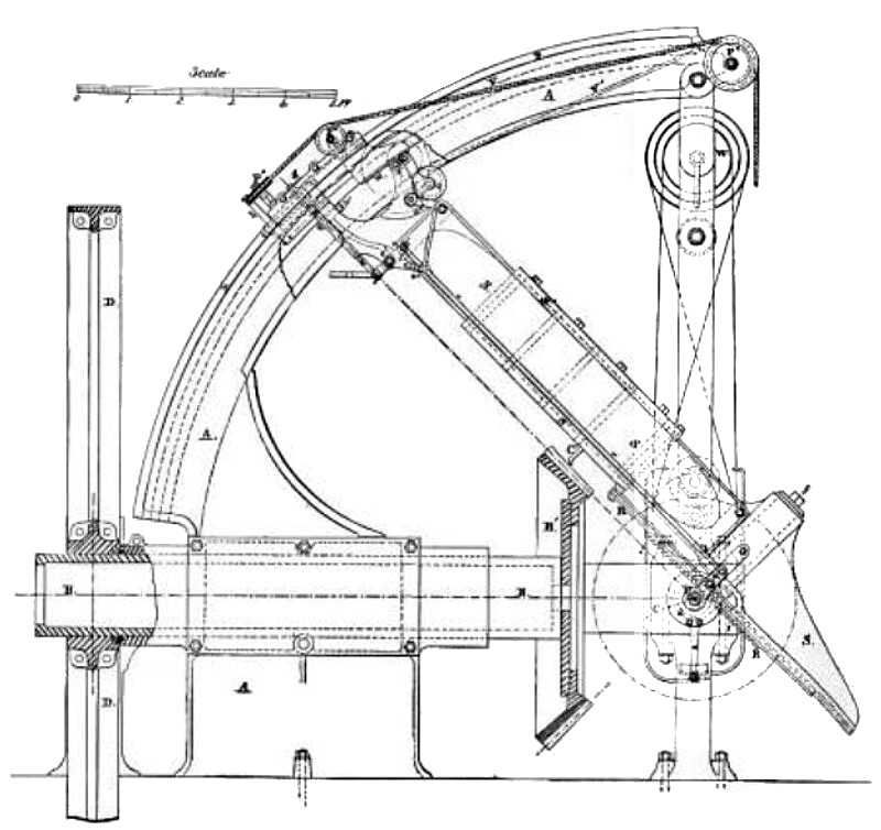
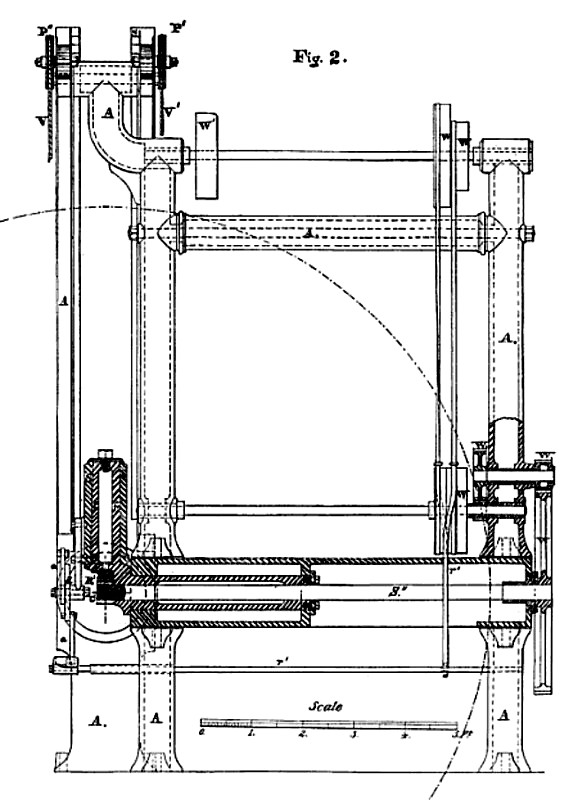
Of the illustration, Fig. 1 is a side elevation, Fig. 2 a front elevation, and Fig. 3 a plan view of the machine—all of them given partly in section to show interior mechanism; Fig. 4 is a side and Fig. 5 a. back view of the device for moving the dividing wheel ; Fig. 6 is a top view, part in section, and Fig. 7 a side view of the feeding and guiding gear; Fig. 8 is an end and Fig. 9 a back view of the mechanism for securing the dividing wheel, and with it the wheel to be cut, at the division used, and for the adjustment of the cut taken ; Fig. 10 is a top and Fig. 11 a side view of the rack and pinion giving motion to the cutter slide, and Fig. 12 is a sectional view of the same; Figs. 13 and 14 are two views of the slotted link for insuring an exact recurrence of the divisions. In these figures, like letters refer to like parts.
A is the frame, and B a large hollow spindle turning therein, to either end of which the bevel to be cut B' and the index wheel D are secured. At right angles to this runs in suitable bearings the shaft 8', carrying a pinion P, to impart motion to the cutter slide S'. Motion is imparted to this shaft in both directions by means of the wheels and pulleys W, W, etc., similar to the driving mechanism of the ordinary iron planer. The shafts S" and B occupy a position such that their intersection is identical with the point of intersection of the lines traversed by the cutting point of the tool. The slide frame S oscillates vertically upon the shaft S" as a centre, its outer end carrying the feeding and guiding gear, being supported as hereafter shown.
This slide frame oscillates also laterally upon the stud f, whose axis also intersects the common point of convergence of the cutting lines. The pinion P gears into a rack R, one end of which is secured to the cutter slide S', and the other sliding in and supported by a prolongation downward of the slide-frame S.
In this way, S is adjustable in all directions upon the centre C, which is the common point of intersection above referred and the cutting point of the tool C', which is made to project the proper distance out of S', must travel in the required converging at C. The cutter slide S' carries upon it a "dog," which comes in contact with collars on the rod r (neither “dog” nor collars shown), adjustable for varying lengths of stroke, which at the require limits gives motion to the arm a’ and disk d, carrying the arm a. On the lower end of the latter is a friction roller traversing an inclined groove, which imparts sliding motion to the rod r", and thus to the belt shippers r” attached to it; in this way the reversing is accomplished just as in the ordinary planer. The rod r at its upper and connects to a lever o, vibrating on the centre 0', to the lower end of which is connected a wedge I. Motion is thus given as well to the arm 0", which connects again with 0'" to operate a ratchet feed through the wheels G and x, the pinion x’, and the circular rack R', the latter being secured to the circular ways y, y, on the frame A.
P is a steel pin vibrating upon the stud p', round on its outer and of wedge form on its inner end; this pin is pressed against a guide or template of steel g, secured to the frame A, having upon its edge towards the pin an enlarged outline of the tooth to be cut, slightly modified to compensate for the round form of the pin; that is to say, the form of this guide is that which the flank and face of the tooth to be cut would have if produced to the some distance from the point of convergence as that occupied by the guide. The pin is kept against the guide by means of the cord V leading over the pulleys P', P', and carrying a weight below the floor. When the wedge I is pushed in at the end of the cutting stroke by the action of the rod r', the whole slide frame, and with it the tool, is moved laterally a little to relieve the tool on the back stroke. The cord V is attached to either one of two levers h, according as one or the other side of the tooth is being operated upon.
Another cord V', leading over pulleys P' P', etc., similarly weighted below the floor, is attached to the upper end of the slide-frame A at A', to counterbalance its weight. W' is the pulley which receives motion from the line shaft.
The tool used in this machine is a modification of what is technically known as a side tool—that is, while cutting down the faces and flanks of the teeth, which, of course, is the principal operation, and for finishing, a very light cut is taken, with the tool made very hard, in order that, in going all round a large wheel—which must be done without change of tool—there shall be no appreciable wear to that very small part of the cutting edge which makes contact with the iron while cutting, for any one setting of it. If this method of cutting bevels has any weak point it is this, and ever precaution must be necessary to insure that the first tooth s taped shall not be smaller than the last from the wear of the tool. To compensate for the very slight wear which must inevitably occur, even under all precautions, the wheel may be gone round in different direction for the different sides of the teeth; at least such a plan would practically correct the wear, every thing being equal.
D is the dividing wheel having index holes on its face (not shown) in several rows, which are divisible for different numbers of teeth. This wheel has teeth upon its edge, into which a small bevel pinion works, driven b a hand wheel H”, for the purpose of moving the wheel from one tooth to another, as shown in Figs. 4 and 5.
A very ingenious and thoroughly good and solid method of securing this wheel to the shaft is that of having two rectangular keys let in to the shaft and hub of the wheel in such a way that two sides and the included angle are in the shaft, while the opposite two sides and included angle are in the hub. These keys are not tapered, but are so placed that they converge towards each other at the point, so that in forcing either inward it reacts upon the other and effectually prevents any possibility of “ backlash” between the wheel and shaft. These keys have projecting head which are drilled to permit of the passage of a stud secured in the hub, upon which a nut serves to force in the keys as desired. This is an extremely solid and reliable plan.
That part of the frame marked B”, Figs. 8 and 9, carries an adjustable jib, L, which is made to bear upon the outer edge of the dividing wheel to prevent lateral vibration; a link, J', Figs. 13 and 14, having at the end which receives the pin J a slot, ending in an offset, and at the other, pivoted to J', is connected to the slide J”. beneath it is a thin plate, K, attached to the under side of the slide, and bearing on the face of D, to prevent its too free motion, as well as forming, on its upper end a limit for the position of the pin J when inserted for a new tooth. When all is adjusted for a new tooth, the pin J occupies the offset end of the slot in the link J’.
This link is adjustable as to length by means of double nut N'. To move from one tooth to another in the wheel being cut, the pin J is removed from the division hole, and the wheel moved, by means of the hand wheel H”, until ' it can again be inserted in the proper hole for the next tooth. To adjust the cut to be taken, the whole indexing arrangement is moved by means of the hand wheel H, shaft H', pinions b, and slide J”, and, of course, remains as set until the wheel has been gone entirely round under the new cut.
The slide frame S, and all attached to it, having a small lateral motion upon the stud f, while the pin p is following the form of the template g, as well as when the tool is relieve upon the back stroke by the wedge I, it is plain that the ordinary solid rack could not work upon the pinion P, and be capable of this lateral motion upon P, as a centre, without causing the teeth to bind; this rack is therefore to permit of such motion made as shown in Figs. 11, 12, and 13. The teeth t t are made with cylindrical shanks which fit easily into holes bored in the bar, forming the body of the rack. They are secured in place by the washer n and screw n', and do not quite touch each other at the shoulders, where they join to form the bottom of the space, in order that, as the frame S vibrates upon f, the teeth in contact with the pinion may have a slight rotation upon their cylindrical shanks, and thus accommodate themselves to the required slight angle through which the slide-frame moves.
Figs. 6 and 7 are enlarged views of the mechanism for feeding down the cut, releasing the tool on the back stroke, and shows the place of attachment of the counterbalance cord at A'.
The history of this machine is quite a peculiar one, and the fact that it was hurriedly designed for an especial case renders the exceptionally ingenious ideas developed in it the more creditable to the designer. When Mr. Corliss decided upon the particular arrangement of the subterranean shafting, which was adopted to transmit the power of his large beam engines to the eight lines of shifting in Machinery Hall, he saw the necessity of having something better for the four large trios of bevel wheels than could be gotten by any methods then in use, if that part of the work was to equal in mechanical perfection and smoothness of performance that which he designed should attach to the remainder of the work. He therefore determined to elaborate the principles of his first patented machine, and incur the large expense as necessary to the production of, for the first time, a machine which should cut such large bevel wheels mathematically as correct as the great spur wheel and its pinion, immediately connected to the engines. This machine was therefore designed after the wheels which they were to cut were in existence, and both wheels and machine have been on exhibition in Machinery Hall, where they were to be seen in operation daily. The very ingenious devices incorporated in this machine, its completeness, perfect working, and the exactness of the work done upon it, together with the production of it in so short a time, and under the circumstances above enumerated, illustrate very perfectly the capacity both of the men and the establishment where it was produced.
(More figures in Parts 2 & 3) |
|
 1876 Corliss Steam Engine Works, Gear Cutter
 1876 Corliss Steam Engine Works, Gear Cutter (Fig. 1)
 1876 Corliss Steam Engine Works, Gear Cutter (Fig. 2)
|
|