|
Title: |
1853 Article-Jenkins & Knight, Spoke Machine |
|
Source: |
Scientific American, V 8 #45, 23 Jul 1853, pg. 353 |
|
Insert Date: |
11/10/2014 10:33:31 PM |
The annexed engravings are views of machinery, for which a patent was granted to Benj. F. Jenkins and Luke L. Knight, on the 4th of last January.
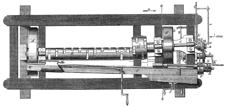
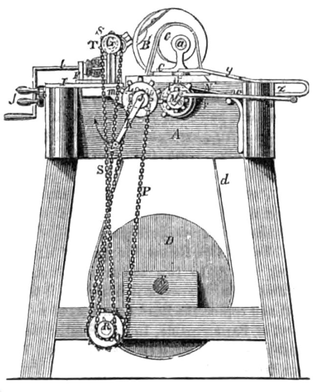
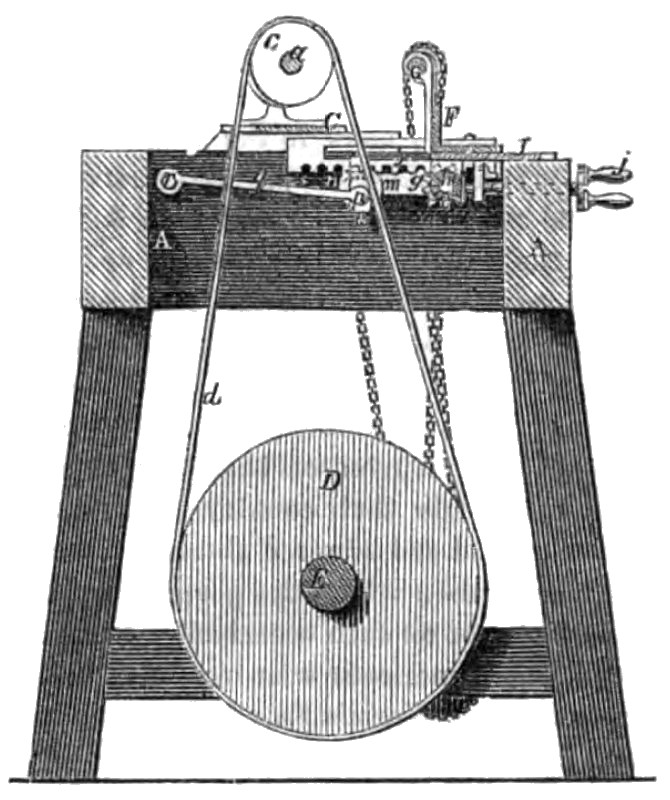
Figure 1 is a plan or top view of a turning lathe, with the improvements; figure 2 is an end view, and figure 3 is a transverse vertical section in the line, x x, fig. 1, looking at arrow 2. The same letters of reference indicates like parts.
This invention relates to that description of turning lathe, in which both the work and cutters revolve, and the irregularity of form is produced by the vibration of the axis of the work, and the whole or part of the cut's; the improvements relate to a simple and effective means of controlling the vibrations of said axes. A is the frame which supports the working parts; B B' are two cutting cylinders: the one, B, has its axis hung in fixed bearings, but the other, B', has a shaft, a, hung in bearings in a head, C, which vibrates from a centre, b, on the frame. The shaft of each cutter cylinder is provided with a pulley, c, which is moved by the band, d, passing over pulley, D, on shaft E. There is a work carriage, F, having suitable heads to carry the revolving mandrel, G, and the movable puppet centre, H. This carriage rests on bed-plate I, and is attached to it by a pivot., e, at one end, the other end being adjustable on the bed-plate by the rack,f, and pinion, g (fig. 3) on shaft h; this shaft gears with a short shaft, z, whose end projects through the front of the frame, and has a handle,/, for turning it. The bed-plate, 1, is pivoted near the end of the carriage, to the frame ; the head of poppet H is adjusted by a screw, k, which is geared by bevel gearing to spindle I, which has a crank handle for the operator. The work carriage receives its vibrating motion through a shaft, J, which is fitted to turn in bearings in arms, m, attached below bed-plate, I. The said shaft carries a disc, n, on whose face there is an adjustable stud, p, which, by being set at different distances from the axis, will form a crank of varying throw. Stud p, is connected by a rod. g, to a stud, v, fixed in the frame. By turning shaft J, with crank handle K, said shaft moves towards and from stud, v, and with it the bed, I, and carriage, F. The bed, I, is kept in a horizontal position, consequently the work carriage vibrates horizontally towards and from the cutter cylinders, whose axes are in the same horizontal plane as that of mandrel, G, and poppet centre, H. On shaft, J, is a wheel, L, with teeth only half around it; on a fixed axis, S, is a toothed wheel, M, of half the diameter of L, but with the same number of teeth (placed on its whole periphery). The wheel, L, gives motion to M, giving one revolution while the teeth are in gear, and causing it to remain motionless while the one half of L is revolving. The wheel, M, is eccentric to its axis, in order to make it continue in gear with L. While the shaft, J, is moving horizontally, it is attached to an adjustable disc, t, attached to disc, u, which is concentric to the axis, and its eccentricity must always correspond with that of stud p. On the outside of the huh wheel, M, is an eccentric pin, v, which is the equivalent of a crank; to this pin a rod, to, connects a rod, y, attached to the end of bead C, the said rod having a guide pin, z, working in a guide in the frame, and which keeps it in place. At the back of disc, u, a spring catch, N, catches in a notch in the hub, and holds the disc so that it will not revolve after the teeth of wheel, L, pass wheel M; but the notch is so formed that it will throw the catch out when power is applied to wheel M, to turn it.
The stuff from which the spoke is to be cut, is shown in dotted lines between the centres; it is caused to revolve by turning shaft J, on which there is a sprocket wheel, O, which communicates motion through a chain, P, to a like wheel (Q), but of double diameter, on a stud near the lower part of the frame. There is another sprocket wheel, R, attached to Q, which gives motion by a chain, S, to wheel T, of the same size, on the mandrel, G. The shaft, E, receives rotary motion from any prime mover (two horse-power is sufficient to drive the machine, and it requires only one person to attend it), at such a speed as will give a high velocity to the cutter cylinders. The piece of stuff for a spoke is placed between the centres and secured; the work carriage, F, is brought to its proper position upon the bed-plate, I, to bring the rough stick up to the cutters. The operator then commences to turn the handle, K, slowly, in the direction of the arrow (fig. 2), giving the shaft, J, two entire revolutions, which, owing to the relative sizes of the sprocket wheels, give the work only one revolution. The eccentric stud, p, causes the work carriage to vibrate twice during the said operations—towards and from the cutter cylinders j the wheels, L M, and rods, w y, raise the vibrating cutter cylinder, B', to vibrate back and forth twice towards the work, but to rest for a short interval each time it is in its furthest position from the axis of the work. The studs, p and t, are so arranged in relation to each other, as to make the vibrating cutting cylinder and work carriage advance towards each other, and arrive at their nearest position to one another simultaneously; but as the cylinder makes its movement in half the time of the work carriage, it commences to move after and finishes moving before it. At the time when the axis of cylinder B' is stationary; between its vibrations, one of the narrow sides of the spoke near the tennon is being cut by it, the work carriage then, making the last half of one vibration backward, and the first half of the next vibration forward. When the axis of B' is moving towards and from the carriage, one of the broad sides of the spoke is cut; the carriage at that time makes the latter half of the forward and the first part of the next vibration backward. As the carriage and vibrating cylinder move towards and from each other twice during every revolution of the spoke, that part of the spoke with which the cylinder comes in contact, will have the form I in transverse section of a four sided figure; the remaining portion of the spoke cut by cylinder, B, will be of elliptical form. By changing the proportions between the wheels L and M, and 0 and Q, and altering the relative positions of the studs p and v, the vibrations of the carriage and cylinder, and the revolution of the work may be so controlled as to produce sections of any desired form, varying throughout the length of the work. One good operator can turn out 200 spokes per hour with this machine. It works without a pattern, and will turn spokes, picks and straight oval handles, of various kinds. It can be altered quickly to turn long and short spokes, it occupies but little room; the frame is less than three by six feet; it is simple, and easily kept in order. The patent is now owned by M. Schoonmaker, and James M. Cooper, Kingston, Ulster Co., N. Y., from whom more information will be obtained by letter addressed, to them at said place.
US Patent: 9,521 |
|
 1853 Jenkins & Knight, Spoke Machine
 1853 Jenkins & Knight, Spoke Machine (End View)
 1853 Jenkins & Knight, Spoke Machine (End View)
|
|