|
Title: |
1853 Article-George N. Stearns & Co., Mortising & Boring Machine |
|
Source: |
Scientific American, V 8 #43, 09 Jul 1853, pg. 337 |
|
Insert Date: |
11/10/2014 1:02:46 PM |
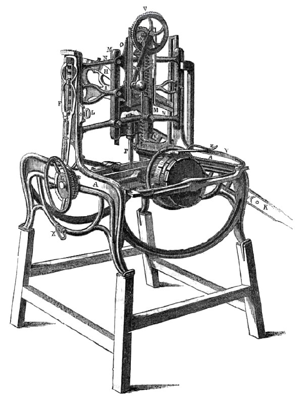
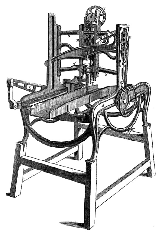
The annexed engravings are perspective views of an improved baring and mortising machine, invented by George N. Stearns, of Syracuse, N. Y., who has taken measures to secure a patent for the same. Figure 1 is a view of one end showing the auger or boring part, the index wheel and hub bed; figure 2 is a view of the opposite end showing the mortising chisel, and the feeding bed for other work than hubs.
A A are the sides of the machine; B, in figure 1, is the bed for retaining the hub to be mortised. It has a rotating index wheel, C, which is turned on its axis—it is also the axis on which the hub to be bored is placed— by the handle wheel, D. The hub is secured on the inner end of the horizontal screw behind wheel, D; Y is a catch to retain the index wheel as it is moved round at any position to form a mortise, and Z is the handle to shift this catch, so as to take it out and fasten it in any of the notches shown on the periphery of wheel C. Figure 2 shows a sliding feeding bed, C, for other work, and a clamp, D, to bold such work down; in these parts it differs from figure 1. The work to be mortised is first bored with the auger, T, and the mortise cleaned and finished by the chisel, P. The auger is operated by a handle, 17, which has a wheel, V, on its axis gearing into a small pinion on the upper end of the auger shank, and gives it (the auger) a rapid rotary motion, during which action it feeds downwards by slides, S, in the grooves in the cheeks of the standards, Q. There is a ratchet wheel, W, on the back end of the auger spindle. This wheel meshes into a rack, R, which by turning the handle, U, in a contrary direction, the auger and its gearing are raised up again—after a hole is bored—to the top of the standards; K is the lever for working the mortising chisel, P, by a reciprocating motion; O is the chisel stock, and M M is an upright guide frame, of which N N are the cross braces, The lever, K, is connected by a link, K', to its fulcrum pin in the side of the machine. At its centre it is united by a link moving in a guide slot in the upright side post to the beam, I, which is attached to and operates the chisel, P. The other end of the beam, I, has a sector rack on it which rocks in guide notches, J, in the opposite upright post; H is a shipper on the upper part of beam I; it is inserted through an opening in the post, and as the beam rocks in it, working the chisel up and down, this shipper moves an open ratchet rod, F, the lower end, 6, of which has two palls on it which take into the ratchet wheels, E E.— One of these palls take into one wheel, E, to move the sliding bed, C, with the work to be mortised on it, in one direction, to feed in the work to the chisel, while the other feeds back the bed. Each pallet is changed to act upon its peculiar wheel by a handle, L, and the shipper, H, moves the rod, F, so as to make the pallet move the wheel, E, one notch for every stroke of the lever, H. There is a cog wheel on the axle of E, inside, which works in a rack oa the underside of the bed, C, and gives a backward and forward motion to said bed by the wheels, E, which are operated by the pallets described, because the notches of one wheel is placed in a contrary direction to those of the other, to be operated by its pallet in the proper direction to feed the work bed, C, back and forth by the movement of the lever as set forth; this is a very useful and ingenuous arrangement; O' is a small lever to change the position of the chisel to cut every mortise properly.
The bed, C, can be set at any angle to cnt a tapering mortise, as the guide rails of the bed, C, are secured on swinging curved supports which have slots in them, and which are set by the screws, X X. The slots spoken of are not seen; they are inside of the frame, but their action, we presume, will be understood.
The nature of this invention consists of two parts, namely, in the simple mode of returning the auger after it has bored a hole by the wheel, W, and the rack, R, as has been described. There is a catch for holding up the slides of the auger stock at the head of the standards, or at any point desired. It also consists in the manner of feeding and reversing the motion of the work bed by the ratchet wheels E E, which are operated by the rod, R, and the shipper, H, worked by the chisel beam, the whole operations being consequent and in unison with the strokes of the working lever, K.
When a hub is to be mortised, as we have stated before, it is secured by the horizontal screw shown in figure 1, and the places for the mortises are first bored by the auger, T the index wheel guiding the hub for the auger to bore in the proper place for each mortise; the mortises are finished afterwards by the chisel, P. The hub bed is capable of being moved forward to bring the hub below the chisel. Other work to be mortised is first bored with the auger, and as the bed C, is not moved except by the operation of the chisel lever, it is stationary while the work is being bored for the mortise first; after that it is moved below the chisel, and operated as has been described.
This machine possesses the quality of mortising hubs, framing, or any kind of work requiring mortising. We have seen a large working machine, and have formed very favorable opinions respecting its usefulness and good qualities. More information may be obtained by letter addressed to the inventor.
US Patent: 14,416 |
|
 1853 Article-George N. Stearns & Co., Mortising & Boring Machine
 1853 Article-George N. Stearns & Co., Mortising & Boring Machine
|
|