|
Title: |
1853 Article-Otis & Cottle, Mortising, Boring & Hub-Boring Machine |
|
Source: |
Scientific American, V 8 #29, 02 Apr 1853, pg. 227 |
|
Insert Date: |
11/9/2014 8:57:10 PM |
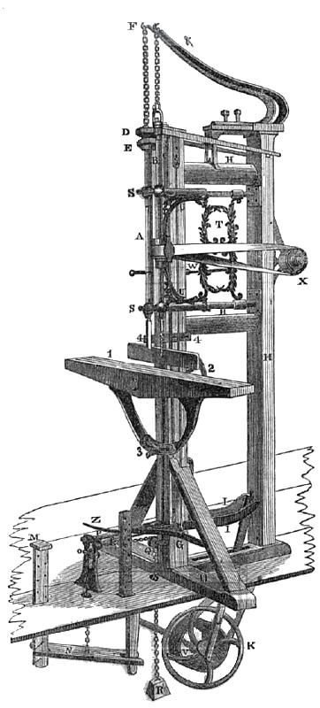
The above is a perspective view of Otis' Mortising and Boring Machine in combination. A represents the mortising or chisel shaft, B, the boring or auger shaft.
The mortising is connected with the power, and operated by it in the following manner:
The side rods, C, one of which is seen in the engraving is connected with the long yoke, D, at the top of the chisel rod, by an adjustable joint, with jam nuts to hold all fast together and keep the side rods of equal length. The two yokes, D and E, are connected together by short eye bolts, which give the yokes full play, yet causing the chisel rod, yokes, &c, to move together in forcing the chisel down into the wood, and to retract the same by the help of the steel spring, F, there is a provision likewise for diminishing the friction between them.
The rods, C, are connected at the lower end to a short slide, G, which plays in a groove in the bottom of the frame work, H H H H H, by a screw. The slide, G, has a steel pin in it which plays in a groove in the movable levers, I I, that are connected by the pitman, J, to the balance wheel, E, the balance wheel causing the levers to make a full stroke at every revolution, but not operating on the chisel rod because the centre of the pin in the sliding fulcrum, L, is cut away, thus causing the centres of motion to be directly over each other, and of course giving no motion to the chisel rod. To bring the chisel rod into play the foot is pressed down on the treadle, M, which carries down the lever, N, and the chain that is connected to it that passes over the little chain pulley, 0, to the sliding fulcrum, L, thus causing the sliding fulcrum with the movable lever, I I, to slide forward on the rods, P P, over the steel pin in the slide, G, and of course carrying down pin and slide rods and chisel rod with it, and allowing the chisel to return again to the same level at every stroke; mortising, of course, deeper and deeper as the levers slide or the resistance is moved further from the fulcrum and nearer the power. The sliding fulcrum is brought back to its former position by the chain passing from the sliding fulcrum over the chain pulley, Q, to the dead weight R, when the pressure of the foot is removed, thus bringing it into full stroke, or five inches, or stopping the chisel at the option of the operator. The chisel rod passes through the guide bolts, S S, the balls of which are lined with babbitt metal. Said guide bolts are connected together by the ornamental brace, T, to which the boring brace, U, is attached, thus causing all the upper work to move in or out together, for any thickness of stuff, and also keeping the back and front boring shafts the same relative distance from each other.
By this arrangement the chisel and auger are always in range, so that the chisel follows the auger, which in mortising hard wood is very desirable. They are held in any desired position by thumbscrews not seen in the engraving.
The boring shaft is operated by a belt coming up from a pulley, T, through friction pulleys, to the short shaft at the back of the machine, on the end of which is a pulley not seen in the engraving. This short shaft hangs in a brace attached to the ends of the guide bolts, and moving in and out with them.— This pulley is made a tight or a loose pulley by a clutch, the shifter of which is seen, at W, thus causing the pulley at X, with its belt running to the boring shaft to revolve at pleasure. The boring shaft is brought down by the rod, Y, and the treadle, Z, and retracted by t he spring, &, and operates with a speed and precision unknown in any other kind of boring machines. The bed, 1, in which the stuff is bored or mortised, is adjustable, being raised or lowered at pleasure for any width of stuff, by the hand wheel and bolt at 2, or made to work on any bevel required by the bevel sweep and nut at 3. The stuff is held back against a guard, and held down by regulating screws at 4 4.
A graduated scale of prices is charged according to what sort of machine is required, for the boring and mortising apparatus can be had separately, as well as with or without the hub rigging, and also adapted for hand work or horse power.
Full particulars of which can be had on application to Otis & Cottle, Syracuse, N. Y.
US Patent: 4,387 |
|
 1853 Otis & Cottle, Mortising, Boring & Hub-Boring Machine
|
|