|
Title: |
1852 Article-Roberts & Pierce, Bedpost Lathe |
|
Source: |
Scientific American, V 8 #14, 18 Dec 1852, pg. 108 |
|
Insert Date: |
11/7/2014 11:35:10 PM |
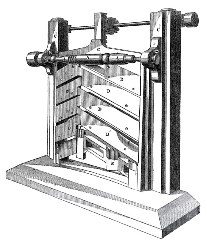
The annexed engravings are views of an improvement in machinery for turning article of an ornamental character but regular form, either plain or beaded, such as bedstead-posts, table-legs, pianoforte-legs, chair stuff &c. The inventor is Milton Roberts, of South Levant, Penobscot Co., Me., who has taken measures to secure a patent. Figure 1 in a front view of the improvement applied to a turning lathe. Figure 2 is a top or plan view of fig. 1, and figure 3 is an end view, showing the stick to be turned with knives and cutters. The same letters refer to like parts on all the figures.
A, in figs. 1 and 2 represents a table-leg, or such-like article, it is centred between the two heads, B B, of an ordinary lathe, and receives a rotary motion by common gearing; C is a rectangular sliding frame, which works up and down in the guides, C'C, which are attached firmly to the lathe bed. D represents a series of knives or cutters placed within the sliding frame, C, in an inclined position. There are two sets of knives in the frame, the
one set being longer than the other, and made to join. By this arrangement they act with a shaving cut when the sliding frame is moved up and down by a rapid motion. The inner ends of both sets of knives incline up wards, and are also a little further from the stock than the outer ends; this makes them act obliquely on the grain of the wood, consequently they make smooth work of it. The two upper knives are placed out in the frame further from the wood than the other knives, and the knives below are set gradually nearer the wood, so that the rough is taken off by the first, and each knife is set in its place to approximate to and finish the stick to be turned, at the end of a stroke. The knives, there fore, have three distinct positions in reference to the horizontal stick, A; first, they are inclined; second, their inner ends are placed out of line with their outer ends; third, they are set in proportion one above the other at a greater and less distance from the stick. E F are tools to make beads and knobs on the stick; they are secured on the lower part of the sliding frame, they are for cutting the beads, &c, on the stick. This stick is represented as finished, the tool, E, cuts the bead, a; the one F the beading, A, and the one G the knob and bead, c. These tools are made of such a form as to cut the desired pattern of beading, &c.; each pattern must have a tool expressly made to cut it out, or the tools may be made in sections, and these joined by screws, so as to change them and make a variety of patterns by the same set of tools.
The lowest set of cutters are so shaped as to cut the general parts of the stick the required form. The two ends, d d, of the stick. A, are tapered, this has been done by the lowest knives, D', which are set at c, so as to form the said tapers.
Supposing the stick, A, to be rough and to receive a. rotary motion by the live spindle set in motion, it is evident when the knife-sliding frame, with all the cutters, is drawn upwards, that the said stick will be cut or shaped by the knives into the form represented. The improvement is a simple and very desirable arrangement of machinery.
More information may be obtained by letter addressed to the inventor.
US Patent: 9,957 |
|
 1852 Roberts & Pierce, Bedpost Lathe
 1852 Roberts & Pierce, Bedpost Lathe (Sectional View)
|
|