|
Title: |
1909 Article-Walker Grinder Co., #2½ Tool Room Grinder |
|
Source: |
Machinery Magazine, V15, Feb 1909, pg. 481 |
|
Insert Date: |
7/28/2014 9:26:11 PM |
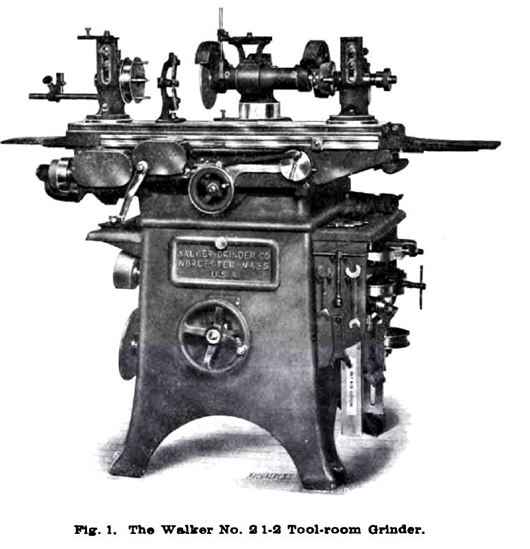
WALKER TOOL-ROOM GRINDER.
The tool-room grinder made by the Walker Grinder Co., Worcester, Mass., is now made in a new design, which is herewith illustrated and described. This new design includes, among other improvements, a new table feed mechanism, and an improved construction of the spindle head, which allows a greater range of adjustment to the spindle without interfering with the free running of the belts.
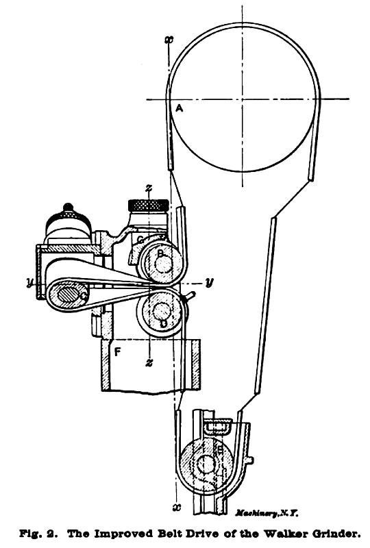
The characteristic feature of the Walker grinder is the provision made for swiveling the cutter spindle in two planes, about a vertical and a horizontal axis. This provision allows the utmost flexibility in setting up work of a difficult character, and renders unnecessary the use of complicated and insecure holding devices for such work as grinding face mills, spiral reamers, etc. The arrangement of this well-known drive is shown diagrammatically in Fig. 2. The belt on the counter-shaft pulley A, passes down to an idler B at the head of the spindle column. From here it passes over the spindle pulley C, back to a second idler D in the column, and down through the lower idler E in the base of the machine. The adjustment for height is effected by raising or lowering the spindle column F. The adjustment of the spindle is about axis xx in one plane and yy in the other. The adjustment about axis xx carries idler E with it, twisting the belt without materially altering its length. Similarly, the swiveling about axis yy is permitted without material change in belt length. The two movements may be made simultaneously, or together, with perfect freedom.
The improvement at this point in the new design consists in mounting idler B (which is flanged, and of about the width of the belt) on pivot G, so that it swings in a vertical axis zz as shown; and in lengthening idler D to permit the belt to travel from one side to the other as required. This permits extreme adjustment without harmful straining of the belts, or rubbing against flanges of the pulleys.
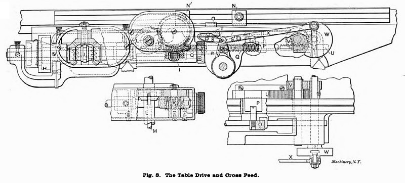
The new cross and longitudinal feed mechanism is shown in the line engraving. Fig. 3. It is driven from the main counter-shaft through a jack-shaft mounted at the side of the machine, which carries a two-step cone pulley connected with that shown at H. This, through the bevel gear and the clutch reversing mechanism J drives the drum K. This drum, in turn, through the gearing indicated, operates the rack pinion shaft L, by means of which the table is reciprocated. A disengaging clutch is provided for throwing out the feed independent of the reversing mechanism by the longitudinal movement of pin M. The reversing is controlled by dogs N and N', adjustable in the T-slot at the front of the table. These shift slide O to the right and left alternately. Projections P and P' on slide O alternately compress springs Q and Q', which press against boss R, attached to the reversing clutch rod. As dog N pushes slide O to the left, for instance, spring Q is compressed but R is prevented from operating the clutch rod under the pressure of the spring, by latch S. This latch is finally released by a cam T on slide O, which allows the spring to suddenly reverse the clutch. For reversing at the right of the stroke, dog N' moves slide O to the right, causing projection P' to compress spring Q'. When it has been compressed sufficiently, T raises latch S' allowing the clutch rod to be thrown over in the other direction, again reversing the mechanism. This arrangement, which is similar to others used for the same purpose, avoids the possibility of stopping on the center.
The automatic cross feed is operated by slide U, which is connected so as to reciprocate with slide O under the influence of dogs N and N'. U has rack teeth cut on its upper surface, engaging with the compound idler gear V. This, in turn, imparts at each reversal a half revolution to slotted crank disk W. The crank-pin adjustably mounted on this disk operates connecting rod X, which thus gives a back and forth angular movement to a bell crank which, in turn, by means of pawl Z, gives a ratchet feed to the cross-feed screw at each reversal of the stroke. The amount of the feed is regulated by the position of the crank-pin in the slot on the face of crank W. For reversing the feed, a similar ratchet to the one shown is mounted behind the bell-crank; it, however, has teeth pointed in the opposite direction. When one pawl is thrown in, the other is out, and vice versa.
In this new design, the best features of the previous machines have been retained. The overhead works is of the multiple speed type, with no step-down of the revolutions per minute, and providing for a wide range of adjustments between the maximum and minimum. The machine is furnished, as shown, completely equipped for cutter grinding, or for cylindrical and surface grinding, thus making it especially useful for tool-room work. |
|
 1909 Walker Grinder Co., #2½ Tool Room Grinder
 1909 Walker Grinder Co., #2½ Tool Room Grinder, Improved Belt Drive
 1909 Walker Grinder Co., #2½ Tool Room Grinder, Table Drive & Cross Feed
|
|