|
Title: |
1863 Article-George Biddell, Steam Traction Engine |
|
Source: |
Mechanics Magazine, 04 Dec 1863, pg. 844 |
|
Insert Date: |
7/7/2014 9:05:27 PM |
BIDDELL'S IMPROVEMENTS IN TRACTION ENGINES.
These improvements, patented by Mr. George Biddell, mechanical engineer, Ipswich, consist in the application and use of a friction clutch or clutches in combination with suitable driving and disengaging gear. The piston rod of the steam cylinder gives motion to the main or crank shaft, on which the friction clutches are by preference placed, although they may be placed on an intermediate shaft, one part having a sliding motion thereon, but always turning with it, whilst the other part which carries a toothed wheel is capable of turning thereon freely when the two friction clutches are not pressed together. On the main or crank shaft is a fly-wheel. The toothed wheel carried by the friction clutches gives motion to another toothed wheel fixed on a second shaft, on which second shall are two toothed pinions which turn with but can slide on that shaft; these pinions are coupled together by a double crank, connecting rods, and forked levers, or other suitable contrivance, in such manner that when one is moved out of gear with its wheel the other is moved into gear with its wheel. The crank by which these two pinions are slid, is on a separate shaft having a lever handle thereon, by which it can be turned in one or other direction at pleasure, and by the interposed mechanism slide the two pinions. One of these toothed pinions works in the teeth of an internal wheel, whilst the other works in the teeth at the periphery of. a wheel of lesser diameter, but both these wheels are fixed on the same shaft. There are also two toothed pinions on this axle or shaft, which rotate with, but are capable of sliding on, the ends of this shaft or axle, so that either or both of such pinions may be in or out of gear with spur wheels carried by the two main road wheels.
These improvements give increased facilities in working; they do away with the usual reversing slide gear, and admit of a single cylinder engine being as efficiently used as one with a double cylinder, thus giving greater simplicity and economy, as also less wear and tear.
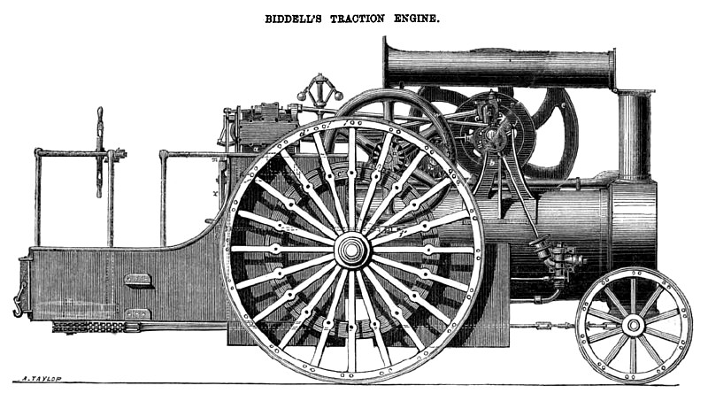
The accompanying engraving, represents a side elevation of a steam traction engine, combined or arranged in accordance with these improvements, a is the steam cylinder of the engine, firmly attached to the boiler and connected with the crank shaft brackets b, b, by the two stay bolts c, c. Motion is communicated to the crank shaft d from the piston by its rod and connecting rod in an ordinary manner, there being guide bars, cross-head, slide valve, eccentric, and parts in connection therewith, also a governor, throttle valve, starting valve, and feed pump—all which are arranged as heretofore. The starting gear, worked by a man at the back of the engine, is of the usual kind, and needs no description, e is the fly-wheel on the engine shaft; f is a small pulley fixed at the end of the crank or engine shaft, both of which can be used for driving suitable machinery when required, as by an ordinary portable engine; g is the external part of the cast-iron friction-clutch, having a cog wheel h securely bolted to it. Upon the largest diameter of this part of the clutch a wrought -iron hoop is shrunk to give additional strength.. This portion of the clutch, with its cog wheel h, is free to turn upon the engine shaft, except when the other portion of the clutch is pressed into it, when it must revolve with that shaft. The whole clutch is kept in its position endways on the shaft by fixed collars. The internal part of the clutch is provided with its six sets of radial knuckle joints and screws and adjusting nuts. This portion of the friction-clutch is always obliged to rotate with the crank shaft of the engine, being carried round by a key, but is capable of sliding endways. The hand wheel m gives motion to a screw through the small pair of bevel wheels, which screw acts directly upon a forked lever, which receives two projections of a collar (made in halves) spanning a recess in the boss of the part i of the friction clutch. By these means the friction surfaces of the clutch can be brought into powerful contact or released with perfect command, thus communicating motion to the gearing at pleasure, whilst the engine is running, and without the necessity of stopping the engine shaft and piston, r is a cog wheel fixed to its shaft s, gearing into the wheel h. The shaft s carries two pinions t and u, which always turn (by means of proper keys) with the shaft s, but are capable of sliding upon it, so as to be put in and out of gear with their respective wheels v and ic, by means of the handle and rod x, and a proper arrangement of levers, cranks, and rods, which arrangement is to be such chat the two pinions i and u shall not possibly be both in gear or in action on their respective wheels at the same time. By one action of the handle x and double crank y, one pinion is always fairly withdrawn from acting on its wheel before the other pinion enters into gear or acts on its wheel. The wheel v and internal wheel w are both firmly fixed to the shaft z, upon which also there are two pinions, which are made to turn with this shaft, but are capable of being moved endways upon it by means of forked levers, so that they can at pleasure be easily engaged or disengaged with their respective wheels, which are firmly attached to the main road or driving wheels. Upon the exterior circumference of the internal wheel w a single clip break is arranged, which is operated upon by means of a hand wheel, and a right and left hand screw.
It will be readily seen that, by means of the friction-clutch and the arrangement of the gearing and the disengaging levers and rods as described, whilst the engines, piston, and crank shaft are running, the forward or backward motion of the entire machine can be started, stopped, or reversed at pleasure without stopping or reversing the motion of the engine shaft and its flywheel, thus giving increased facilities and obvious advantages in using the power of the engine. |
|
 1863 George Biddell, Steam Traction Engine
|
|