|
Title: |
1887 Article-W. & S. Eddington & Co., Steam Traction Engine |
|
Source: |
The Engineer Magazine, 21 Jan 1887 pg. 47 |
|
Insert Date: |
7/2/2014 1:58:23 PM |
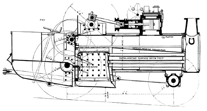
EDDINGTON AND STEEVENSON’S TRACTION ENGINE
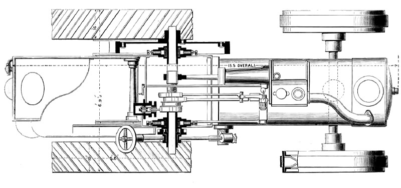
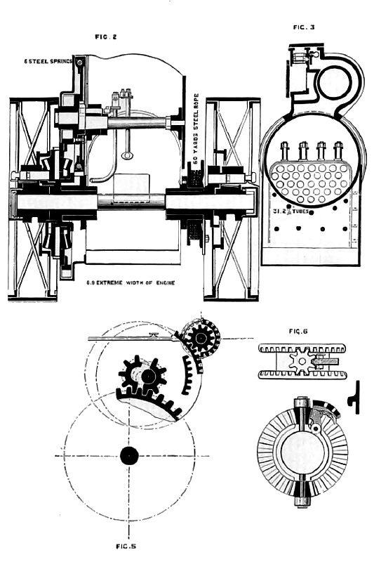
We illustrate on page 47 a traction engine constructed by Messrs. Eddington and Steevenson, of Chelmsford, which was exhibited last December at the Smithfield Club Show. This engine contains several novel features. It is made to travel at two speeds in the ratio of 11 to 18, by an entirely new method of change which will be understood by reference to the engraving, Fig. 5. The second-motion shaft in made with an eccentric end, so that by turning about one-third of a revolution it moves the centre of the second-motion wheel, so that it can put into gear with the slow-motion pinion in one position, and when in another it is in the right position to slide the fast-speed pinion over the other into gear, so that both pinions gear in the same wheel. It will be understood that the centres are at equal distances from the centre of main axle, so that in each case the large driving wheel is in proper gear with its pinion. Some of the advantages of this
arrangement are as follows:—(1) The ratio of 11 to 18 is better than 2 to 1, which is that usual where one pinion slides over the other; (2) the engine can he made narrower; (3) both pinions are close up to the bearing when in gear; (4) saving in weight of the engine, the shafts being shorter are stronger; (5) the slow-speed pinion is keyed tight on to the crank shaft and does not slide; (6) only one fork: lever is used. The boiler is divided by a plate from the smoke-box end to a point nearly over the front end of the fire-box. The steam having travel a considerable distance horizontally over the plate, is admitted to the cylinder in a very dry state, thereby, it is claimed, avoiding priming, and when an engine is descending an incline prevents the water from ?owing off the fire-box to the front end of the boiler. The introduction of springs between the driving and driven parts of the second-motion wheel, which, it is claimed, prevents back-lash and noise, and takes up any sudden strain on the gearing, rendering the teeth less liable to fracture. The cylinder is the only part of the engine fixed to the boiler by bolts. The engine is very narrow, only 6ft. 9½in. over all, though the wheels are of full width. The wheels are made of wrought iron, with steel tires and strakes. The compensating motion on the main axle can be locked in a second by a very simple arrangement, which will be understood on reference to Fig. 6. The wearing surfaces are made very large, the crank shaft brasses being 10in. long, the one extending inside the ?y-wheel, as shown in Fig. 1, and the other inside the gearing; the connecting-rod brass is 6in. wide; the axle bearings are 12in. long. The crank shaft is made of the best best scrap iron, and bent out of the solid bar, and is 3½in. diameter throughout. The piston is of improved construction, the rings and centre piece are free to revolve, it wears the cylinder very evenly, and the rings cannot break. The winding drum, Fig. 2, is on an independent bearing, and remains stationary when not in use. The rope can he attached to a load and the rope run off as the engine proceeds, and when at the top of a hill the drum is put in gear and the load hauled up by the rope. The centre of the cylinder in very low and close to the boiler, whereby the strain caused in working is reduced, at the same time a long reversing link in used; this is attained by placing the motion shaft above instead of below the centre. The fore-carriage is made on the principle of a ball-and-socket joint, the opening being of the right size to prevent the wheels locking too far. The arrangement is very simple, and the engine steers very easily. A powerful brake in fitted on each hind traveling wheel, so that whatever breaks on the engine or comes out of gear the man can always stop even on the steepest incline; it can also be used for fixing the engine when hauling with the rope. The engine is fitted with the makers patent removable lagging, which can he taken off and replaced in an hour without damage, also their patent water gauge, which shows the water in the glass down to the dangerous point, at the same time the bottom hole is placed the top of the fire-box. The cylinder in steam-jacketed; the liner in made of very hard metal; the space round this is excessively large, and forms a. capacious steam dome, admitting the steam to the cylinder in a very dry state. |
|
 1887 W. & S. Eddington & Co., Steam Traction Engine (Sectional View)
 1887 W. & S. Eddington & Co., Steam Traction Engine (Top View)
 1887 W. & S. Eddington & Co., Steam Traction Engine (Rear View)
|
|