|
Title: |
1886 Article-A. Shirlaw & Co., Spiel's Petroleum Engine |
|
Source: |
Scientific American Supplement, V 21, 03 Apr 1886, pg. 8,535 |
|
Insert Date: |
7/1/2014 4:08:43 PM |
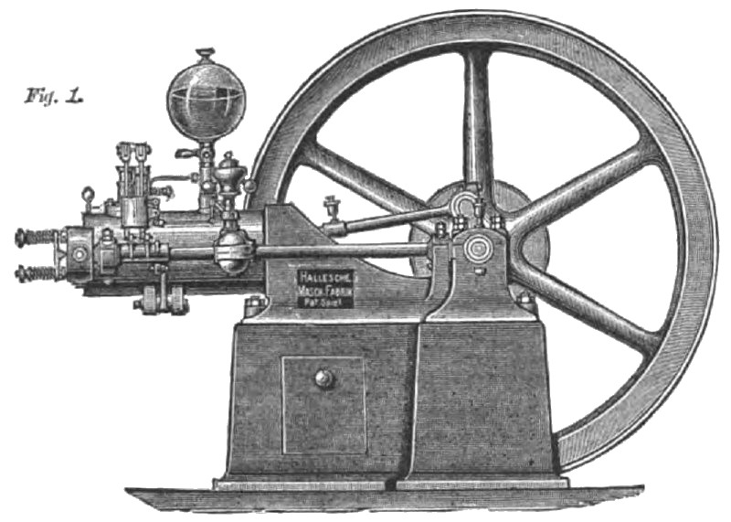
SPIEL’S PETROLEUM ENGINE
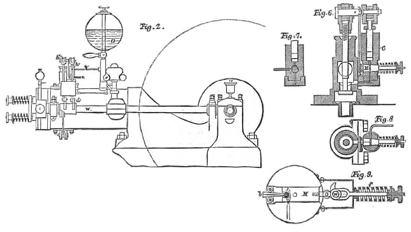
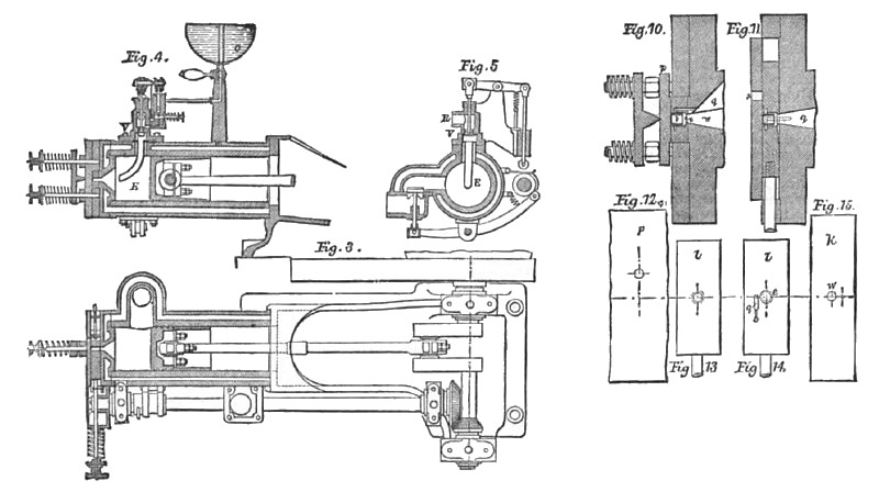
A very neat and successful form of petroleum engine, invented by Mr. Johannes Spiel, of Berlin, has, says Engineering, lately been introduced in London. The cycle of operations is that with which the reports of the gas engine law cases have familiarized all the world; the piston on its out-stroke draws in a charge of air and petroleum; it then returns, compressing this mixture, which is exploded as the crank es the back center. be next stroke sees the combustion and expansion of the charge, while the fourth and last stroke of the cycle drives out the products of combustion. There is thus one acting stroke in every four. the motion being continued through the other three by the energy stored in the flywheel. The source of power is petroleum spirit, otherwise known as benzoline, and also as naphtha. This has a specific gravity of 0.7 or 0.71, and a very low flashing point, so t at it will not pass the Abel test; consequently it cannot be stored and used without special precautions. If the proper conditions are observed, the use of this spirit does not involve any extraordinary risk, for it is employed in large quantities in the dry cleaning process, and also in the manufacture of India rubber. When used with this engine, it is stored in a enclosed receptacle connected by a pipe and hand pump to the reservoir, O, Fig. 2. From this reservoir there runs a pipe to the pump, k (Figs. 2, 3, and 6), by which measured quantities are injected into the cylinder. At the bottom of the pump there is, in place of a foot valve, a plug, a (Figs. 6, 7, and 8), worked by a link from a tappet, as will be presently explained. During the induction stroke of the piston, the cock is turned into a position which permits the liquid in the ump to gain access throng the passage, z, to the space above the inlet valve, N, while at the same time the admission of liquid through the pipe, n, from the reservoir, O, is cut off. During the remaining strokes of the cycle the cock occupies such a position as to cut off the communication with the valve, V, while the pump is again placed in communication with the reservoir, O. The petroleum does not pass through the plug but along a channel cut round it. The passage of the oil or spirit from the pump, k, to the cylinder is past the valve, V, and through the pipe, . The air enters by the branch, R, and in passing the valve, V, it drives forward the spirit, breaking it into fine globules, and carrying it into the cylinder in admixture with itself. The curved gutter, t, Fig. 6), formed round the mouth of the pipe, E, serves to arrest any liquid that may be imperfectly mixed, and as the explosive mixture flows over it, and beneath the valve, the gutter tends to direct the current upward so as to break up and still further mix the air with the liquid. The valve, the pump, and plug, a, are operated by a cam on the shaft, w, which is driven by bevel gear, and revolves at half the speed of the crankshaft. A crosshead, h and h', is connected to a rocking beam, which at its other extremity carries a rod ending in a roller, which runs in contact with the cam, and is raised at the appropriate times. A spring draws down the roller when the projection on the rain has passed. Another portion of the cam opens the exhaust valve (Fig. 5). The firing valve (Fig. 9) consists of a plate, M, operated by a tappet on the end of a shaft, w. The valve spindle is prolonged and provided with a spring by which the valve is shot back when the tappet ceases to act on the friction bowl. The force of the recoil is moderated by the spring stops, b, which run between the rollers, g g, and must be compressed as the valve nears the end of its stroke.
The firing light is the flame of a lamp which is kept constantly burning. At a suitable moment it ignites the burner in the valve, and by the quick return movement a flash is transported to the firing apparatus in the cylinder. The combustible mixture finds its way into the burner during the compression stroke. In front, and surrounding the burner, is a chamber, e (Figs. 10 to 12), which serves to convey a flame from the outer jet, i, to the charge in the cylinder. The chamber, e, forms an annular space round the burner, and the passage, q, opens into this space, and maintains a communication for the supply of the combustible gas or vapor during the times when the main passage, w, is closed. The gas passing through q flows round the burner, and thus becomes heated and ignites more readily.
When the chamber is filled with gas, the valve, l, is moved by the ram, d, until the burner, b, is opposite the port, z, in the cover, p. The gas is then ignited by the outer flame, and continues to burn during the return stroke of the firing valve until the chamber, e, comes opposite the passage, w, when the charge in the combustion chamber of the cylinder is ignited. The maintenance of the firing flame is effected by the flow of gas through the passage, q. The engine at present in this country will work up to 3½ brake horse power, with a consumption of about one quart of benzoline per horse power per hour; the same rate of consumption is also obtained if the power he reduced to two horse power. At the rate of 8d. per gallon, this represents an expenditure of 2d. per brake horse power per hour. The motor works very satisfactorily, does not clog in the valves or cylinders, and bids fair to find a good field where gas is unattainable and the local rules concerning the storage and transport for petroleum spirit are not too stringent. |
|
 1886 A. Shirlaw & Co., Spiel's Petroleum Engine
 1886 A. Shirlaw & Co., Spiel's Petroleum Engine (Section Views)
 1886 A. Shirlaw & Co., Spiel's Petroleum Engine (Section Views)
|
|