|
Title: |
1887 Article-A. Shirlaw & Co., Spiel's Petroleum Engine (part 1) |
|
Source: |
The Engineer Magazine, 21 Jan 1887 pg. 54 |
|
Insert Date: |
6/30/2014 8:51:35 PM |
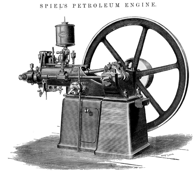
SPIEL'S PATENT PETROLEUM ENGINE
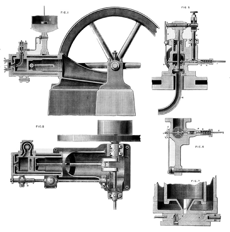
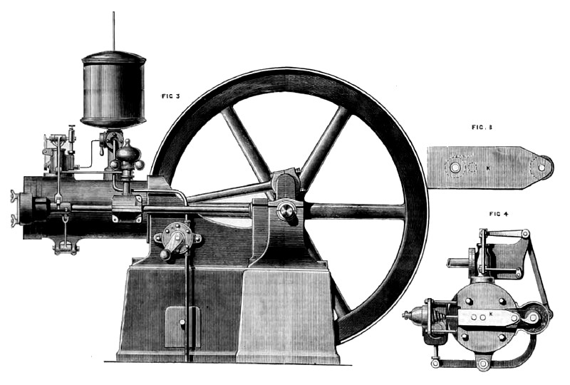
By the engravings on page 50, and those annexed, we illustrate Spiel's petroleum engine as made in Messrs. A. Shirlaw and Co., Birmingham. In the engravings on page 50 Fig.1 is a longitudinal section of the cylinder, air valve, &c.; Fig. 2 in a ground plan of engine, with cylinder in section showing exhaust valve; Fig. 3 is a general elevation of engine, and Fig. 4 an end elevation allowing the levers by which the air valve and oil pump and exhaust valve are worked; it also shows the firing valve arrangement; Figs. 5 and 6 are enlarged views of air valve, oil pump, and governing arrangement; Figs. 7 and 8 are enlarged views of firing valve. The supply of petroleum is drawn from a cask or drum, which may be kept in any convenient place by the rotary hand pump A, Fig. 3. And delivered through the pipe B to the reservoir C which supplies the cylinder direct through the pipe F.
The action of the engine is as follows: At the first, or induction stroke, the cam M, Fig. 2, is in a position to just open the air valve D, Figs.1 and 5. The piston then draws in behind it a supply of air through the valve D; at the same time the oil plunger E descends and measures in a definite quantity of petroleum. At the end of this first out stroke the air valve D closes and the oil plunger E is lifted ready for another supply.
The mixture of air and oil that is thus measured into the cylinder is taken down through the tube H, Fig, 1 and 5, where it is thoroughly mind before entering the cylinder. During the second, or compression stroke, the mixture is compressed by the piston to about three atmospheres, and when at the end of the compression stroke is exploded by the firing valve K, Fig. 4. The next out stroke in the power or working stroke, and at the end of this the exhaust valve its opened by its lever and cam L, Fig. 4. During the next return stroke the cylinder in cleared of the products of combustion and at the end of this stroke the cam M, Fig. 2, is again in a position for another induction or charging stroke. The manner in which the petroleum is admitted into the cylinder is as follows: The crosshead N, Fig. 5, has a certain amount of vertical travel through the cam M and lever O, Fig. 4. In Fig. 5, the valve P is held open by the spring R, which at the same time holds the valve P1, shut. This admits the petroleum through the pipe F underneath the plunger E. When the crosshead N descends the roller S catches against the projection T, which has the effect of pressing the lower end of the lever U against the ram V, which closes P and opens P1, before the crosshead N touches the plunger E at W; then the plunger E descending forces the petroleum through the open valve P1 against the cam X, which breaks it into a spray. It is then carried along with air down the pipe H.
The governing is arranged in the following manner. When the engine revolves above its normal speed, the governor, by an arrangement of wipers and small rocking shaft, forces the slide Y, Fig, 6, forward till the thick part of Y covers the end of the ram V, so that when the bottom of the lever U presses inward, the ram V is not touched, therefore the valve P1 remains shut and the valve P remains open; then when the plunger descends the petroleum is forced through the open valve P and the pipe F to the reservoir C instead of to the cylinder. It will be seen from this that when the governor acts, air only gets into the cylinder, and thus there are no explosions till the engine falls to its normal speed, when the governor also falls, and again a spray of oil is admitted into the cylinder. The igniting valve K, Fig. 4, has about one inch travel, and is forced forward by the hooked cam on the right of the sketch, and shot back by the volute spring on left. In the section Fig. 7, supposing the piston is at the beginning of the compression stroke, the chamber Z in opposite the opening to cylinder Z1. When the pinion compresses, it forces a quantity of the explosive charge into the chamber Z, and by the time the piston is at the end of the compression stroke the hooked cam referred to has forced the valve along till it is in the position shown in sketch Fig. 7, and opposite the opening in valve cover Z2, which in filled with a spirit lamp flame. Here the mixture in chamber Z in ignited, and the hooked cam leaving its roller allows the volute spring to shoot the valve back, carrying with it a flame in chamber Z which explodes the charge of air and petroleum in the cylinder. When the hooked cam has moved the chamber Z out of communication with the aperture Z1, the small slot K, allows a stream of the explosive mixture to pass to Z, which keeps the flame in Z alight. The indicator diagram, Fig. 9, in from one of these engines, indicating 3.45-horse power and giving at the some time 2.24 brake horse power, the engine running at 245 revolutions per minute and being of 1-horse power nominal. Fig. 10 is from an engine of 2-horse power nominal, indicating 5.5-horse power, and giving on the brake 3.25-horse power actual, the speed being 210 revolutions per minute. The highest pressure in Fig. 9 is 112 lb., and the average pressure 57.6 lb., while the average of Fig. 10 is 61.5 lb. with a maximum of about the
same.
An experimental test run was made with one of these engines some time since, by Dr. J. Hopkinson, F.R.S. The diameter of the cylinders of the engine tested was 5 7/8-in.—l5 cm.—and the stroke 11in.— 28 cm—. The diameter of the ?y-wheel is 4-ft. 11-in. A suitable friction brake, loaded with 28lb., was fitted on the ?y-wheel, and the engine was run with this load for over five hours. Dr. Hopkinson, in his report, says:—"The engine was not stopped during the run, and it was found that at the end of the experiment all the bearings were cool, proving that the engine was by no means overloaded. The piston was taken out, and the interior of the cylinder examined and found to be in a perfectly satisfactory condition. The run lasted from 12.36 to 5.40, or 304 minutes. The consumption of petroleum was 25 pints in 303 minutes, or 4.95 pints per hour, 0.0825 per minute. The lubricating oil consumed was a minute quantity in excess of half a pint. The weight on the brake corresponds to a uniform rate of working of 2.87-horse power effective. The specific gravity of the petroleum in 0.7, and I have ascertained that it can be bought at from 6½d. to 7d. a gallon. From this experiment many interesting conclusions may be drawn, both as to the practical value of the engine, and as to the way in which it compares with other engines from a scientific point of view.. The engine tested is easily able to develop 2.87-horse power on the brake without pulling up, and without heating any bearing in continuous work of five hours. The consumption of petroleum is with this rate of working 1.724 pints per horse-power per hour, and the cost of such oil at, 7d, per gallon, in 1½d. per horse-power per hour. The cost of lubrication would be less than ¼d. per horse-power per hour. It is, however, interesting to examine further the significance of these figures ; French weights and measures are adopted, as the calculations are more easily made and more easily verified by others. Most of these we omit. as few of our readers will be disposed to agree with Dr. Hopkinson as to these French figures. “The nominal 2-horse power Otto gas engine in of very nearly the same size as the engine tested, and may form a basis of comparison of the two engines. The gas engines of the same size an Spiel's engine tested by me would, when running 160 revolutions per minute, indicate 4.1-horse power, and give about 3-horse power on the brake. It would consume of London gas about 50 litres per minute with a heating value of 280.000 gramme degrees; thus the dynamical efficiency of Spiel's engine is, when run as when I tested it, very slightly less than that of an Otto gas engine of the same size; 50 litres of gas per minute is 106 cubic feet per hour, costing in London 3.8d. or 1.27d. per effective horse power per hour. It is worthy of remark that petroleum is hardly any dearer than London gas as a fuel. The engine has been worked out into a thoroughly practical form, and is now fit to be trusted in the hands of users of power with the same confidence as the best gas engines."
Since Dr. Hopkinson's test was made, Messrs. Shirlaw have, we are informed, been able to make a further reduction in the consumption of petroleum. and to increase the brake horse power as compared with the indicated. These recent. attainments are given in the foregoing. The indicator diagrams show that without. an excessive initial pressure an effective, steady, and well maintained pressure is obtained throughout the stroke.
A considerable number of the engines have now been at work some time, and Messrs. Shirlaw and Co. have devised the vertical form shown by the accompanying engraving, which illustrates a three-man power engine occupying a ground space of only 18-in. square. A horizontal 1-horse nominal engine is, we are told, driving a twenty-two 20-candle incandescent lamp installation. |
|
 1887 A. Shirlaw & Co., Spiel's Petroleum Engine
 1887 A. Shirlaw & Co., Spiel's Petroleum Engine
 1887 A. Shirlaw & Co., Spiel's Petroleum Engine
|
|