|
Title: |
1859 Article-Neptune Iron Works, Schultz's Steam Engine |
|
Source: |
Scientific American, V 1 #13, 24 Sept 1859, pg. 201 |
|
Insert Date: |
5/25/2014 8:11:51 PM |
IMPROVEMENT IN STEAM-ENGINES.
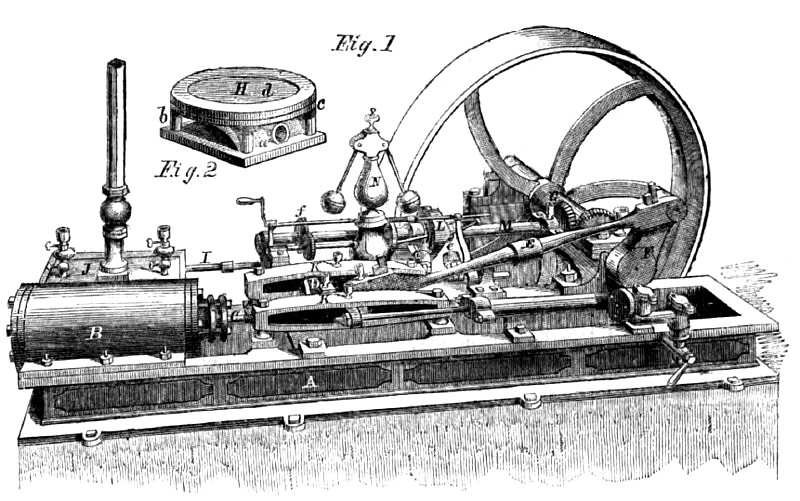
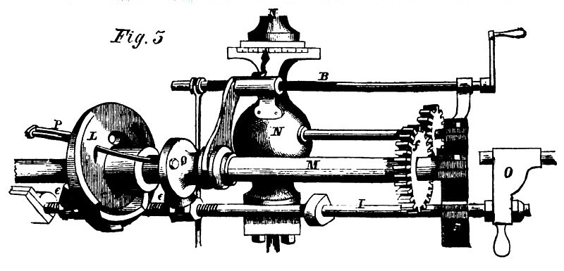
The steam-engine, as it is the most useful machine of 'the present day, receives its duo and proper share of attention from the inventor, and is continually having changes made in its construction, some of which are for the better and others cause simply additional expense without giving any improvement or saving. When therefore a real improvement is placed before the reader for consideration it should be carefully examined and criticized, and the subject of the accompanying illustrations will bear this close scrutiny. It is the invention of C. A. Schultz, of New York City, and will be seen in perspective in Fig. 2; Fig. 3 (5) being a view of the back of the other side of the engine, also exhibiting the working parts of the invention on an enlarged scale.
A is the framing, B, the cylinder, and C, the piston-rod, attached to a crosshead, D, which works in slides, K K. To the crosshead the connecting-rod, E, that gives motion to the crank, F, on the shaft, G, to which the fly-wheel is secured, is attached. J is the steam-chest in which a balance slide valve, II, (the subject of a separate patent) is placed. This valve is seen separate in Fig. 2. The body, o, is the same as the ordinary slide valve, and four columns, b, rise from it, supporting a plate, c, and cap, d, which is so placed as to allow c, to move freely up and down; springs in the upright columns keep the face, a, against the cylinder, and the plate, d, against the top or cover of the steam-chest, and no steam can enter between the cap and the cover of the steam-chest.
I is a valve-rod, which has two friction rollers, e, placed in a suitable position on it, and between which a double cam-wheel, L, rotates, so as to give the valve rod the back and forth motion by the action of the cam on the friction rollers as it rotates. The wheel L, is placed on a shaft, M, that is placed in suitable bearings on the side of the frame, A, and derives its motion from the bevel gearing on its end and the shaft G. A gear wheel also placed on it gives motion to the horizontal shaft that causes the governor, N, to rotate. The rod, I, can be connected or disconnected with the valve-rod, I', by means of the simple clutch or holder, O, or by any other convenient means.
Each cam-wheel has a slot and a small hole in it, the hole of one being opposite to the slot of the other, so that the bent V-shaped yoke, F, can pass through the holes and be free to move in the slots. This yoke is attached to a collar, Q, that can slide on the shaft, M, and that has a nut provided with a pointer through which the screw rod, R, passes, connected with it; so that by turning the rod, R, the yoke can be made to pass in the holes to distend the cams, and thus give the engine more steam, or can be retreated to bring the cams more together to cut off at any desired point to give the engine less steam. An index attached to the governor pillar allows the exact number of inches at which it is desired to cut off to be exactly obtained. This rod, R, is also operated from the governor by a rod, S, and a bell-crank connection (not seen), so that the governor instantly corrects any variation in the speed of the engine from work being put on or thrown off, or from other causes.
The inventor has built an engine and it is now on exhibition at the Fair of the American Institute at the "Palace Garden" in this city. We have seen it work and have seldom seen any engine which ran so smoothly and economically, as the steam can be used with any amount of expansion of which it is capable, and any required speed steadily and continuously kept up. We would state that the engine may be reversed at will by the engineer, and operated in either direction as the work requires.
The patent on the main part of the engine is dated October 26, 1858, (#21,907), and the patent on the slide valve is dated April 19, 1859, (#23,714). The inventor will be happy to give any further information upon being addressed at the Neptune Iron Works, foot of Eighth-street, East River, New York. |
|
 1859 Neptune Iron Works, Schultz's Steam Engine
 1859 Neptune Iron Works, Schultz's Steam Engine (Mechanism)
|
|