Image
|
Title: |
1876 Article-Aveling & Porter, Steam Road-Locomotive |
|
Source: |
Reports of the Commisioners of the United States, 1876 pg.89 |
|
Insert Date: |
3/23/2014 9:06:06 PM |
The writer made a public trial of these engines and a steam road-roller by the same builders (Aveling & Porter) in October, 1872, at South Orange, N. J., which was attended by the commissioners of public roads for the neighboring county, and by many members of the engineering profession from New York and other cities. Two road-steamers, or traction-engines, and a steam road-roller were brought out for exhibition and trial.
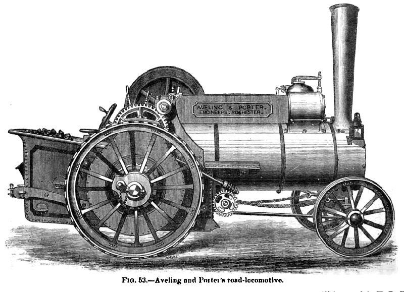
No. 1 was a new road-locomotive (Fig. 53) built by Messrs. Aveling & Porter; it had previously done no real work. A sketch of this machine is here given. It was of precisely the same size and pattern of one of those exhibited at Vienna, and above referred to. The following description will apply to both: Principal dimensions:
Weight of engine complete, 5 tons 4 cwt., pounds 11,648
Steam cylinder, diameter in inches. 7f
Stroke of piston, inches 10
devolution of crank to one of driving-wheels 17
Driving-wheels, diameter in inches 60
Driving-wheels, breadth of tire in inches 10 Driving-wheels, weight, pounds, each 450
Boiler, length overall, feet 8
Boiler, diameter of shell, inches 30
Boiler, thickness of shell, inches ^
Boiler, fire-box sheets, outside, thickness in inches g
Load on driving-wheels, 4 tons 10 cwt., pounds 10,080
The boiler was of the ordinary locomotive type, and the engine was mounted upon it, as is usual with portable engines.
The driving-pinion on the crank-shaft was made capable of being slipped out of gear, thus allowing the engine to be kept in motion when the locomotive was at rest, either to pump water into the boiler, or to drive as a " portable engine" by a belt which could be carried on the pulley, 4J feet in diameter and 5 inches face, which was fitted to act as a flywheel. When used as a "portable engine," regulation was effected by means of a fly-ball governor conveniently attached. The cylinder was steam-jacketed in accordance with the most advanced practice here and abroad. The crank-shaft, and other wrought-iron parts subjected to heavy strains, were made of Lowmoor iron, and were strong and plainly finished. The gearing was of malleableized cast-iron, and all bearings from crank-shaft to driving-wheels, on each side, were carried by a single sheet of half-inch plate, which also formed the sides of the fire-box exterior. This simple device united all parts peculiarly exposed to injury by jarring, with such firmness as would seem to give perfect security against such injury even on rough roads. The engine valve-gear consisted of the standard arrangement of three-ported valve and Stephenson link, with the reversing lever, as used on locomotives. The feed-pump was driven by an eccentric keyed on the crank-shaft. The connection between the gearing and the driving-wheels was effected by one of the neatest and most ingenious devices known to engineers. This arrangement is called by builders of cotton machinery a "jack-in-the-box" gear, and the "differential" gear. As constructed, one wheel turns freely on the driving-axle, while the other driving-wheel is keyed fast. A bevel-gear is bolted on the hub of the wheel, and a similar gear is keyed to the driving-axle. Between these revolves a spur-gear, which is driven by the engine, and which carries two small bevel-pinions, the latter engaging both bevel-wheels, their axles being in the plane of revolution of the large gear. Resistances being equal on both wheels, if the spur-gear be turned it will carry with it both driving-wheels at the same time with equal angular velocities, the effort exerted by the engine being equal to both wheels at all times. If the engine be turning a corner, however, the greater resistance on the inside wheel retards that, while the outer wheel necessarily moves more rapidly over its longer path, and, while the engine still exerts the same force on both wheels, the work done is distributed unequally between them through the then revolving bevel-pinions, without loss, and without either wheel being necessarily slipped or disengaged. Should one wheel, however, strike into a soft spot, as a patch of muddy soil, and finding so little resistance as to turn freely, leaving the opposite wheel at rest on firmer soil and thus checking the motion of the locomotive, a heavy bolt, which is furnished with each machine ready fitted to its place, is inserted and keys the loose wheel to the shaft. Both wheels must thus turn together until, the locomotive being extracted, the bolt is withdrawn. Such an occurrence is seldom likely to take place.
The driving-wheels were wrought-iron, strong but light in their construction, and were fitted with strips of iron, thickest at the middle of their lengths, which were laid diagonally across the face of the wheels, with separating spaces of about two inches between them. The angle was such that one end of one strip would come to a bearing on the ground just as the opposite end of the preceding strip was leaving it.
The builders claim that this method of obtaining tractive-power in the wheel gives the engine a pulling-power, on good ground, equal to 0.45 of the insistent weight. On extremely hard and smooth roads, bolts are inserted in the wheel-rim, whose heads give better holding power than even these iron strips, and on very soft ground the same bolts are used to secure to the rim of the wheel pieces of angle-iron, called by the builders "paddles," which take a good hold on the more unstable kinds of soil. The weight of this locomotive rested principally upon the driving-wheels. About 15 percentum was left upon the forward axle, to insure good steering power. The total weight on the drivers was somewhat increased, when pulling a load, by the inclination of the line of traction downward from the pulling-bolt to the point of attachment to the load.
The forward axle is fitted with wheels of 42 inches diameter and 8 inches face; it swings about a king-bolt, which is secured above in a bracket secured to the under side of the boiler smoke-box, and is steadied by a strong rod, connecting its lower end with the forward end of the fire-box. Chains led from each end of the axle to a shaft carried on the forward end of the fire-box, around which they wound in such a manner that turning this shaft would swing the axle. A hand steering-wheel, conveniently arranged near the throttle and reversing handles, turned this shaft, being connected with it by means of a worm-shaft and pinion. A tank at the rear of the locomotive carried coal and water in its compartments, and afforded a standing place for the engine-driver, from which he could readily reach the various handles and gauges. Draught was secured by means of the exhaust.
The boiler and steam-cylinder were both well protected against losses of heat by coverings of felt and lagging. No springs were used on the engine exhibited, as, being intended for heavy work at slow velocities, their advantages would not justify the expense and complication attending their use. A strap-brake was fixed on the driving-axle for the purpose of controlling the engine on heavy grades. |
|
 1876 Aveling & Porter, Steam Road-Locomotive
|
|
|
|