|
Title: |
1892 Article-Kempsmith Mfg. Co., Universal Horizontal Milling Machine |
|
Source: |
Modern Machine Shop Practice, V2, 1892, plate III |
|
Insert Date: |
12/9/2013 3:15:09 PM |
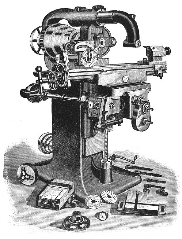
Plate III. represents Kempsmith's new Universal Milling Machine.
The general design of the machine conforms to the usual practice, but in the details some departures have been made which are interesting from a mechanical standpoint. The cone pulley has its smallest end nearest the main bearing, in order to allow of the frame of the machine being brought up close to the bearing, to give it the greatest possible strength there, and the overhanging arm is fitted to a socket, which is bored in an arch extending from one upright to the other, and cast solid with the frame, two clamp bolts securing the arm firmly in place, and at the same time permitting it to be readily removed when desired, and a stiff and solid machine is had, whether using the arm or not. Six changes of feed are provided for with each different speed of the spindle, the slowest speed of the latter being suitable for a cutter i inch in diameter, back gears, proportioned 4 to 1, being used for the larger sizes.
The index or spiral head is so arranged that its spindle may be elevated, or depressed below the line of centres, has a full line of index plates, and is geared to cut spirals from one turn in 1 1/3 inch to one turn in 133 1/3 inches, the gearing being arranged either simple or compound, as may be required, the simple gearing being sufficient for all the ordinarily used spirals, this gearing being arranged the same as the change gears on a lathe, and put in place with equal facility. The foot stock is fitted with what is called the side centre, this being so arranged that it offers the greatest possible facility for getting at the work with cutters, either at the top or at the side.
The three squared handle stems seen in front of the knee are for the usual vertical and horizontal movements, there being two rates of vertical movement of the knee provided for, one slow and the other rapid, the latter for use when the knee is to be moved a considerable distance. The table can be swung clear around, and clamped at any desired angle, and has automatic feed at any angle, or in either direction, the feed being automatically tripped at any desired point in either direction. The table is fed by a splined screw, which derives its motion from bevel gears, the table swinging upon a central trunnion A, Fig. 3, Plate IV., and being clamped at any angle by the split ring B, which is made of steel. The trunnion is firmly screwed and doweled into the swivel block C, and is bored to receive the hollow vertical shaft D, through which shaft passes the feed trip rod E. The feed is tripped by dropping a worm out of gear, and trips as easily when under the heaviest cuts as when running light. An end view of the worm, worm-wheel, and case, partly in section, is shown at Fig. 1. The direction of the feed is reversed by turning a knob to the right or left, this knob being shown at the left of the lever G, Fig. 2, and in section in Fig. 3. The reversal is accomplished by means of a double-ended clutch, which engages with bevel gears running in opposite directions. The feed worm is of hardened steel, runs in oil, and its shaft in phosphor bronze bushings. The feed is thrown in by lever G, and out by latch H, when operated by hand, and by a trip pin, when used automatically. The feed gearing is completely enclosed, to protect it from dust or chips, and the opening in the top of the knee is at all times covered by sliding plates of steel.
With the head and foot stocks removed, the top of the table is entirely unobstructed, so that work of any length may be fastened to it.
The spindle, which is of steel, is hollow, and the end threaded; arbors or chucks which fit this spindle fitting also the spindle of the index head. The movements of the table by the screws are indicated in thousandths of an inch by micrometer graduations, the index marks on the movable collar being the same as those on the graduated circle, so that they match exactly, and there is no projection nor obstruction of the graduations. |
|
 1892 Kempsmith Mfg. Co., Universal Horizontal Milling Machine
|
|