|
Title: |
1863 Article-Root's Steam Engine Co., Rotary Steam Engine |
|
Source: |
Scientific American, V 08 #5, 31 Jan 1863, pg. 65 |
|
Insert Date: |
12/5/2013 9:38:26 PM |
Improved Rotary Engine.
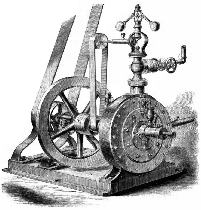
The annexed engraving is an illustration of Root's rotary engine, which, from what we have seen of it, seems destined to occupy a place among the useful inventions of the day. A rotary engine which would possess durability and economy equal to the reciprocating engine now in common use, is a thing which has been much sought after heretofore, but not, however, with much success. The advantages of an engine of this kind, if so perfected and introduced into use, would be very great, and this is acknowledged, so far as we know, by all who are conversant with the subject. Among the advantages are great diminution of cost, saving of room and weight, &c. The above engine has been in use at different places in the city for over a year past, and we are told that the results obtained in regard to durability and economy are truly remarkable in an invention of this kind.’ The invention is covered by several patents which are in the hands of a company, who have established a factory at No. 9 Adams street, Brooklyn, N. Y., and they are turning out about one 15-horse engine per week; other sizes will soon be completed.
By referring to the letters the relation of the several parts will be understood. They consist of the hollow bed-plate, A, to which is bolted the cylinder, B. The cylinder head, C, has a long boss or hearing, D, cast upon it, through which the piston shaft, a, projects. Upon this shaft is the collar, b. The bearing is tapped on each side and at the bottom, and has set screws,c, inserted so that the integrity of the piston, with reference to the bore of the cylinder, is at all times insured. The set screws, whose heads are seen at d, are those by which the side packing regulating apparatus at the top of the cylinder is always maintain the same position, relatively, with ring is adjusted The set screw, e, means for tightening the abutment packing between the exhaust and steam openings of the cylinder. The very similar to that usually furnished with steam engines and has no uncommon features. At the further end of the bed-plate are the brackets or pillow blocks, supporting the shaft, fly-wheel and pulleys, through which the power is transmitted. The shaft coupling, E, has two ribs, crossing each other at right angles, one on each side, which forms universal joint and prevent the piston shaft from springing through any irregularity of strain on the pulleys.
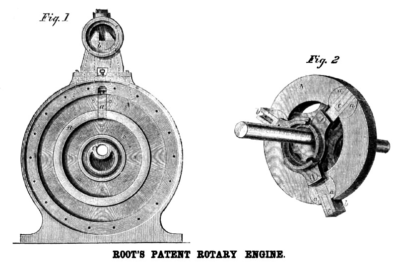
Figs. 1 and 2, in section, represent views of the interior of the cylinder of the piston, its D-valves, wings and guide rings. In Fig. 1, A, is the inner face of the cylinder; B is the side packing ring which packs the surfaces between the piston and cylinder head, and C is the eccentric or guide which keeps the wings in contact with the face of the cylinder as the piston revolves. At a may be seen the abutment packing. The valve, b, in the chest, c, at the top of the cylinder, is that one by which the motion of the piston is reversed. Fig. 2 represents the piston and its shaft. It is a cast-iron wheel, A, divided at regular intervals by the D-valves, a, in which slide the wings, b. These are rectangular pieces of cast iron having grooves in each side and upon their faces in which the metallic packing, c, is fitted; this packing is pressed outwardly to the cylinder by spiral springs in each. The pistons are connected at their base by circular guides, d, to the ring, e, to which they are accurately but easily fitted. Over these guides another ring is applied, which keeps them in place.
These details comprise the main features of the invention. It will be seen that when steam is supplied, the piston revolves by the action of the steam upon the wings. The piston is net concentric with the cylinder, but eccentric, consequently some means must be furnished whereby the ends of the wings shall always maintain the some position, relatively, with the bore of the cylinder; these means are found in the employment of the D-valves, a. As the piston revolves around the eccentric, C, the pistons, being jointed to the guides, slide in and out through the D-valves; these oscillate sufficiently to maintain, at all
positions of the piston, a true bearing of the packing.
The patents for this Invention were procured through the Scientific Patent Agency. Further information may be had by addressing Root's Rotary Steam Engine Company, No. 33 Pearl street, New York.
Patent #34,393. |
|
 1863 Root's Steam Engine Co., Rotary Steam Engine
 1863 Root's Steam Engine Co., Rotary Steam Engine
|
|