|
Title: |
1863 Article-Dole & Silver, Hub Boxing & Spoke Tenoning Machines |
|
Source: |
Scientific American, V 09 #8, 22 Aug 1863, pg. 113 |
|
Insert Date: |
12/5/2013 7:25:20 PM |
Hub-Boxing and Spoke Tenoning.
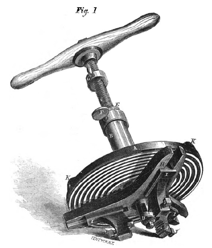
Many operations in the arts, which to all intents and purposes are manual, can be greatly facilitated by the introduction of simple and efficient tools. The annexed engravings are representations of very excellent tools of their class; and will be found valuable aids to the wheelwright and wagon-maker. Fig. 1 is a perspective view of the hub boxing machine. It is self-adjusting, strongly made, and not at all clumsy or awkward to handle. The operation and construction of the several parts will be easily understood, by referring to the subjoined description.
The self-centering machine is provided with a scroll-plate, A, which turns freely on a hollow stem, B. This stem is fitted with a mandrel, C, one end of which is furnished with a strong handle, while the other extremity has a mortise, D, cut through it, in which the cutter is placed. The upper end of the hollow stem is chambered out, and has a feed-nut, E, let into it, which is secured by the set screw, F, working in a groove in the body of the nut. The gage, G, on the thread, affords a ready means of regulating the depth to which the cutter works. On the scroll-plate may be seen a triangular plate, H, having forked ends, in which the chucks, I, slide; the feet of the game being grooved to fit the plate. The ends of these chucks are creased, and fitted with set screws, J, so as to hold the machine on the hub without shifting its position. When it is desired to use the tool, the wrench provided for the purpose is inserted in the holes, K, in the scroll-plate, which is revolved until the chucks, I, open wide enough to grasp the hub. As they all move from the center, the bit, or cutter, is always in the proper place when the jaws bite the hub; this is attained by setting them up forcibly against the work with the wrench aforesaid. This machine is made in several sizes, to suit the capacity of the work to be done; and will materially lessen the time and labor heretofore expended on this portion of the wheelwright's duties.
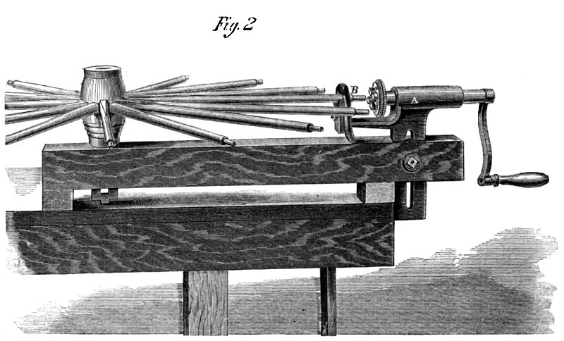
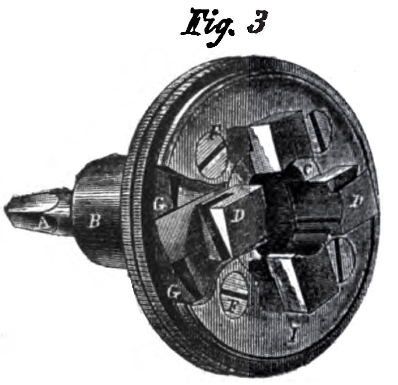
The hollow auger, or tenoning machine, Figures 2 and 3, is also a very simple and useful tool, and requires very little detailed description to render its construction intelligible. The operation of it can be seen at a glance by referring to Fig. 2. It is fitted up in two different styles; the character of the tool remaining the same in both. In Fig. 3, the tool is shown as fitted for use in a common carpenter's brace; having a squared shank, A, screwed into a metallic socket, B; this socket is a part of the metallic disk, C, in which the cutters, D, are placed. The arrangement of these cutters, and the ingenious method by which they are set out to the size it is desired to make the tenon on the spoke, are worthy of special notice. The milled edge of the brass ring, H, enables the workman to turn it (by slacking up the small screws, F, in the face-plate) so that the curved projections, O, inside, bearing on the end of the cutters, force them in toward the center of the tool. The cutters also have a slot in them, which fits over and under the plate I; so that by tightening the screws, F, the cutters are retained firmly in their places. The arrangement in Fig. 2 represents the bench attachment, where the hollow auger works through a bearing, A; the end of which is provided with a dog, B, to hold the end of the spoke, while the hub of the wheel is fastened to the opposite end of the frame. A small bolt working through the slot in the bearing, A, serves to regulate the height of the machine to suit the different kinds of hubs. The tenoning machine is also adapted to boring felloes, being provided with a chuck for holding auger bits, that screws on the same mandrel in which the hollow auger is held; in the end of the mandrel is a square socket to receive the bit. The chuck is also provided with 3 set screws, which tighten against the shank of the bit, for the purpose of truing it, and preventing its being withdrawn from the socket.
The felloes are held by a screw clamp, so that they may be bored perfectly true, and fit upon the shoulders of the spokes without straining the tenons; thus making a better and truer wheel than is possible by the common method; doing the work much faster, and with but little labor. Patented on Jan. 10, 1860. For additional information, address the manufacturers, Dole & Silver, Salem, Ohio ; or Cornelius Van Horn, 29 Park Row, New York. |
|
 1863 Article-Dole & Silver, Hub Boxing & Spoke Tenoning Machines
 1863 Article-Dole & Silver, Hub Boxing & Spoke Tenoning Machines
 1863 Article-Dole & Silver, Hub Boxing & Spoke Tenoning Machines
|
|