|
Title: |
1895 Article-Mann & Charlesworth, Steam Traction Engine |
|
Source: |
Engineering Magazine, V 59, 28 Jun 1895 pg. 829 |
|
Insert Date: |
11/6/2013 1:02:02 PM |
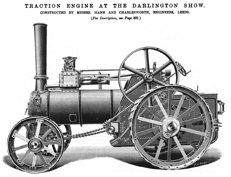
Among the makers of engines, Messrs. Mann and Charlesworth, of Dewsbury-Road, Leeds, hold the leading position on the score of novelty, as they are quite a young firm, and appear for the first time at a Royal Show. They exhibit both traction and fixed engines (see illustrations on page 829). In the former, in view of the keen competition that awaits all beginners, they have studied the question of economy as far as it can be done without sacrificing efficiency. As an example, they have substituted for the link motion, with its expensive rods and pins, a single shifting eccentric, the construction of which will be understood from the illustration (Fig. 2). The eccentric has a large eye, which enables it to be shifted from full gear forward to full gear backward, and set in any intermediate position, the motion being in a straight line, so as not to vary the lead in the intermediate positions. The eccentric D is carried by two very broad links B and C, whose width is equal to the diameter of the shaft. To these it is pivoted by long pins that allow of no "shake." These links are pivoted to lugs cast in a wheel which is keyed on the shaft, and in this instance used as the governor pulley. It will thus be seen that the eccentric is driven by the links. To fix its position in relation to the shaft, one of the links, B, has a second arm, or pair of arms, that convert it into a bell-crank. At the ends of the arms are jaws connecting them with lugs on a sleeve E, which can be slidden along the shaft by means of a lever. When the lever is at the end of its travel in either direction the valve motion is in full gear, while at intermediate points the gear is notched up. As explained by Mr. Joy in his recent paper before the Institution of Mechanical Engineers, an eccentric of this kind has a constant tendency to go into full gear. Hence it is possible to relieve the rings in the groove of the sleeve of all friction, at the two ends of the travel, by arranging that the sleeve shall come against fixed collars. At the intermediate positions there is, of course, some friction, but it is not great. If the catch be lifted out, the reversing lever can be easily held in any position, showing that the sideways pressure on the sleeve is not great. The engine itself is of a light 7 horse-power type. It has fast and slow pinions, sliding on the squared end of the shaft, with bearings at each side of them. The main axle has also squares to receive the bevel wheel and winding-drum.
At the same stand is a tandem compound horizontal engine, with a shaft governor, which we illustrate on page 829. This is an adaptation of the same idea as that found in the valve gear of the traction engine. The eccentric is carried by two links like those we have just described, and is not pivoted to a long arm, or banjo frame, as is often the case. One of the weights has a curved projection formed on it, and this takes into a slotted die fitted to the eccentric. The curve is struck to such a centre that when the weight moves in and out it has to shift the eccentric so as to increase or reduce the cut-off, according to circumstances. It will be seen that, although the weight has perfect command over the eccentric, yet the pressure exerted by the eccentric on the weight passes so nearly through the centre on which the latter turns that it can have little or no effect in determining its position. The effect is that this governor works satisfactorily with a fiat slide, and does not demand the use of a balanced valve |
|
 1895 Mann & Charlesworth, Steam Traction Engine
|
|