|
Title: |
1895 Article-Fielding and Platt, Portable Hydraulic Riveting Machine |
|
Source: |
Engineering Magazine, V 59, 19 Apr 1895 pg. 604 |
|
Insert Date: |
11/3/2013 1:32:33 PM |
TRAVELLING HYDRAULIC RIVETING PLANT
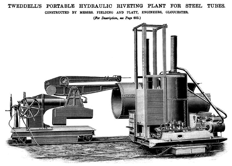
The illustration on page 604 represents an hydraulic riveting plant designed by Mr. Ralph H. Tweddell, of 14, Delahay-street, Westminster, S.W., and sent out in 1892 to work in connection with the Sydney Western Suburbs Sewerage Scheme, New South Wales. The tubes which it was designed to rivet were used on the aqueducts and approaches over the Cook's River and Wolli Creek bridges (steel structures made to carry them), and on the low-lying lands between the Rocky Point Road and the north bank of Cook's River. These mains were 7/16 in. thick and the plates 8 ft. long, the diameter of the mains being 6 ft. The rivets, {in. in diameter, were all closed by hydraulic pressure as the mains were laid. The riveting plant consists of a power trolley, on which are placed duplex pumps boiler, coal bunker, rivet-heating furnace, and an accumulator loaded to 1500 lb. per square inch. The trolley is supported on suitable wheels 4 ft. 8} in. gauge. A second trolley carries the riveting ma chine, this being of somewhat special construction, having a gap of 8 ft. 6 in. It has two riveting cylinders, one on the frame and the other on the hob. Each cylinder is of sufficient power to deal with i - in. steel countersunk rivets, and has its own working valve. A plate-closing fork is also fitted to each ram, so that either may be used as a plate-closer according to circumstances. The machine is mounted on a strong bracket, and is balanced by a counter weight, so that it can revolve easily on a gudgeon which works in a standard on the trolley. By means of suitable worm gearing the riveter can be readily revolved, and thus enable the dies to travel round the pipe, when doing the circumferential seams. The wheels are so proportioned that one turn of the handwheel moves the cupping dies the exact distance or pitch of rivets. When the longitudinal rivets are being driven, of course the whole trolley and riveter are simply travelled along the line, and the movements correspond to the pitch of rivets as before. Owing to the two mains being placed within 15 in. of each other, the working room of the outer riveting arm was very limited. The water is conveyed to the riveting cylinders by means of a flexible copper pipe, as shown, from the accumulator, and being taken through the centre of the gudgeon on which the riveter turns, the whole machine is free to revolve in any direction for any desired number of revolutions. The exhaust water is similarly dealt with, and returns to a tank under the power trolley. The total weight of the power trolley is 16¾ tons, and the riveter trolley 20¾ tons.
The machine was guaranteed to rivet up 50 lengths a day, but it easily accomplished 60 in that time. The rivets are all put in from the inside, and at the manufacturer's works at Gloucester, the rivets were put in at the rate of 2000 rivets per day of 10 hours. The fact that this plant was sent out without any spare gear, except leather moulds and fire bars, and finished the contract without a hitch, speaks volumes for the quality of Messrs. Fielding and Platt's workmanship. The whole plant was erected and worked without the assistance of any one from this country. The pumps and accumulator are equal to working two or three riveters, and it was only under protest from Mr. Tweddell that only one riveting machine was sent to such a distance for so large a contract, seeing that had anything happened to the machine all would have been laid aside ; however, fortunately, all went well, and the entire arrangement is one well calculated to show the advantages of hydraulic riveting. The machinery was supplied to the order of Mr. James Smith, Billiter House, E.C.; Mr. George A. Goodwin, M. Inst. C.E., Whitworth Sch., of Victoria-street, S. W., being the inspecting and superintending engineer on behalf of the Sydney authorities. |
|
 1895 Fielding and Platt, Portable Hydraulic Riveting Machine
|
|