|
Title: |
1895 Article-Ferracute Machine Co., Power Stamping & Coining Presses |
|
Source: |
Engineering Magazine, V 59, 19 Apr 1895 pg. 508 |
|
Insert Date: |
11/2/2013 7:22:10 PM |
POWER STAMPING AND COINING
PRESSES
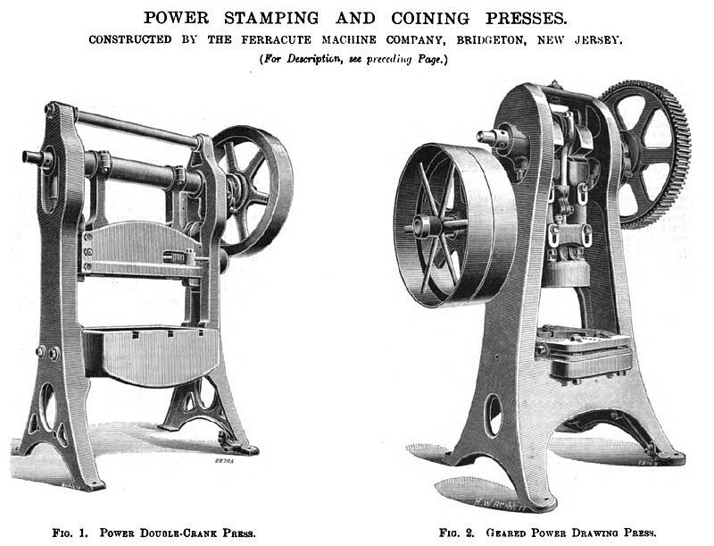
There are illustrated on pages 508 and 509 several presses for coining and stamping manufactured by the Ferracute Machine Company of Bridgeton, New Jersey, a company which has made a specialty of this machinery.
The power double-crank press, shown by Fig. 1, has, as its name implies, double cranks and pitmans, which adapt it for very large work without danger of the ram being tipped to a position out of parallel with the bed. It has a composite frame of a construction allowing great variety of sizes and shapes of rams and beds, with the same columns and other smaller parts, thus enabling them to be changed much more quickly and in greater variety than would be the case were the frames cast in one piece. There is a very long adjustment of ram operated by two worms mounted upon a diagonal shaft, which engage respectively in two worm-gear nuts mounted upon heavy slides, which are pivoted to pitmans with solid metal joints, these nuts being split part the way through that they may be firmly clamped on to the threads of the above-mentioned slides by means of conical sleeves which contract them by being forced down upon them. This device can be operated with one hand, even while the press is in motion if desired, and insures perfect parallelism between ram and bed, which can be maintained indefinitely, in spite of wear, by the adjusting screws provided.
Fig, 2 illustrates a geared power drawing press with a cast-iron A-frame. The flywheel, 44 in. in diameter by 7 in. face, and making 180 revolutions per minute, is keyed to a 3 7/8 in. steel back shaft running in solid bearings. To this shaft is keyed a cut pinion with 15 teeth, 14 in. pitch, which gears into a spur-wheel with 90 teeth. The spur is keyed to the main cam shaft; this shaft is 4J| in. in diameter, and runs in split cast-iron bearings. The main slide is worked by a cam thrown in contact with G in. cast steel rollers of 4J in. face, moving in phosphor bronze bearings in a roller bracket which is bolted to the ram working in the main slides. The drawing ram is worked by a crank, with 8-in. throw, with bearings 7 in. in diameter by 7 in. wide, it being a round slide in the main ram. A spring bolster, actuated by four studs, is placed on the table for facility in setting the dies. There are the same points as in the press shown by Fig. 3, omitting the inclinable feature and the stay-rods, and adding the feature of back gearing, which, by the way, may be applied to almost any of the company's presses.
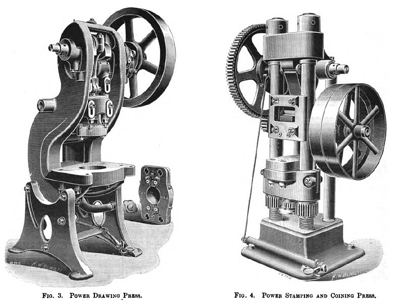
The drawing press illustrated by Fig. 3 has a frame so mounted upon its legs as to be quickly inclinable to any desired angle by a convenient elevating screw, and proper clamping nuts for securing the same. Its construction is unusually heavy and strong, and has very carefully proportioned parts, especially in regard to large shaft diameter, very long cam and roller bearings, short distance bridged by shaft between its bearings, kind of steel used in cams and rollers, method of ram adjustment, plunger adjustment, automatic lifting of ram, &c. It is claimed by the makers that these details avoid difficulties inherent in, and objections incident to, cam presses as heretofore made. Experience has shown that presses of this kind are simpler and moie durable than those in which the ram and plunger are driven from the shaft through the intervention of moie complicated devices, providing the precautions above mentioned are carefully taken. It is true that many cam presses have been weak and "springy," but this has probably been due to imperfect designs rather than to the principle involved. I here is a spring ram-lifter arranged with an equalizing lever, so that the lifting is practically equal all the way up, together with a positive lifting device connected with pitman, so that the cams cannot leave the rollers in case the spring lifter should fail. A ram is fitted with a very large hole for deep punches to pass up into, and yet with solid metal whereto upper dies may be fastened by the hooked clamps provided, together with a plunger having a large and long hole for shanks of punches, with a locking arrangement which moves them positively up and down, but allows sufficient play, so that they may enter their dies accurately and centrally, while at the same time leaving room to put in bushings to fit various odd punches which may be required. There is a bolster with a deep and heavy truss extending down into the bed of the press, so that it may remain perfectly flat, and yet can be tipped slightly out of level at its different corners by four sliding wedges driven by screws and nuts, while at the same time its thin and elastic edges are firmly clamped to the bed of the press, thus enabling dies to be accurately aligned to each other to prevent wrinkling of work. A pair of stay-rods can be quickly inserted in the frame, thus making the press nearly as stiff as a straight-column press, upon certain occasions where great rigidity is required, and where it is not necessary to pass long sheets through sidewise, as is usually done in throated presses.
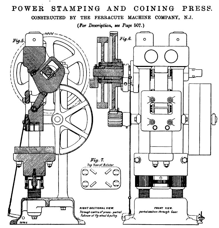
Fig. 4 is a general view of a power stamping and coining press, while Figs. 5 to 7, on page 509, show the details of the machine. The power is transmitted by a 5-in. belt to the flywheel, and from thence through a cup spur-wheel and pinion to the toggle lever. The press is massive in construction, a cast iron base and head being connected by two 5-in. tension-rods.
A positive clutch operated by small rods and a pedal is used for working the press, the pedal being depressed to make each stroke. The spur-wheel has a large boss, into which four steel pins 2¼ in. in diameter, standing out 11/16 in., are fixed; these are ranged 3¼ in. apart, and have four hardened steel pins 1¼ in. in diameter placed between them, these latter being held out from the face of the boss by springs. A concentric collar on the shaft carries a sliding-pin 1 1/16 in. in diameter, held towards the boss by a V-shaped spring. A swinging plate fastened to the main casting, but on a shaft, carries the clutch lever used for withdrawing the pin. In its normal position the clutch is latched, and the pin has to be withdrawn to stop the automatic running of the press. |
|
 1895 Ferracute Machine Co., Power Stamping & Coining Presses
 1895 Ferracute Machine Co., Power Stamping & Coining Presses
 1895 Ferracute Machine Co., Power Stamping & Coining Presses
|
|