|
Title: |
1895 Article-A. Ransome & Co., Landis Horizontal Log Band Saw |
|
Source: |
Engineering Magazine, V 59, 05 Apr 1895 pg. 438 |
|
Insert Date: |
11/2/2013 12:24:36 PM |
|
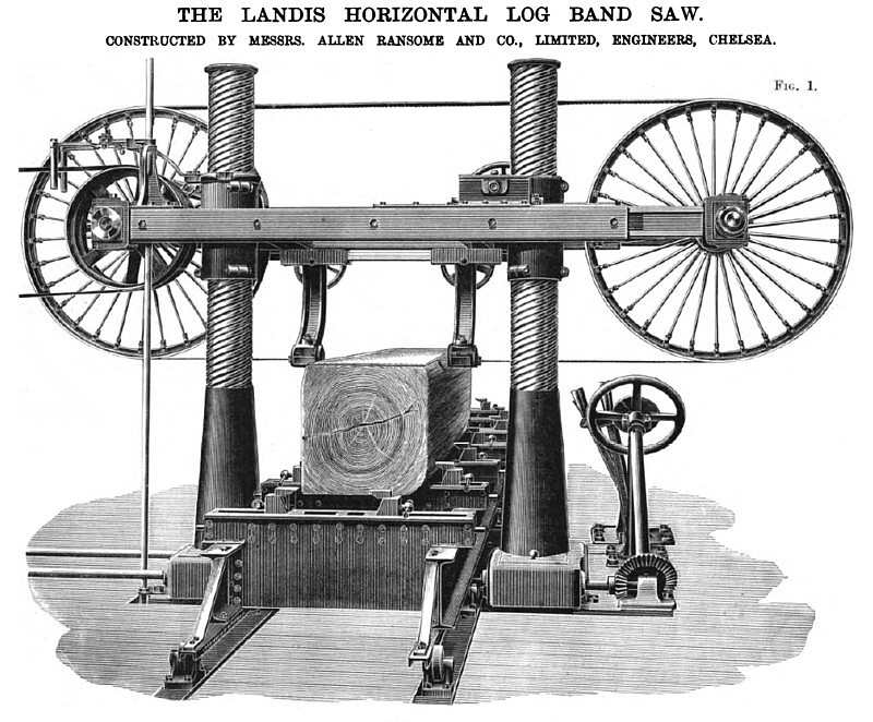
The band saw which we illustrate on this page has been patented by Herr Landis, a sawmill owner, whose works are situated near Zurich, and the machine is now being made by Messrs. A. Ransone and Co., of the Stanley Works, Chelsea. As will be seen from our illustrations, the saw cuts horizontally instead of vertically. The frame of the machine consists in the main of two pillars fixed on each side of the log table. Surrounding each pillar is a sleeve, on the upper portion of which a multiple-threaded screw is cut, whilst at the bottom of each sleeve a worm-wheel is fitted. These wheels are driven by two worms keyed on a shaft extending transversely across the machine underneath the table. Cutting is commenced with the saw in its highest position, and as each plank is cut off the saw is lowered by rotating the hand-wheel shown on the right, which is connected to the worm-shaft already mentioned by bevel gearing. The weight of the saw and its saddle, the pitch of the screw being quick, tends, it will be seen, to make the manipulation easy. A dial is fitted above the hand-wheel, and permits the thickness cut to be accurately regulated. The saw is raised again by power. The bearings supporting the pulley spindles are fitted on trunnions. Each of these trunnions, in the case of the right-hand pulley, is fitted on an arm, sliding telescope fashion in the main saddle casting. On the top of these arms a screw rack is cast, into which a worm gears, which afford a means of sliding the arms out and of getting the requisite tension in the saw. In order that the saw may run properly, however, it is necessary that the two spindles shall not be parallel to each other, and it is for this reason that the trunnion bearings are employed. The worm traversing the back telescopic arm can be uncoupled from its fellow in front, and this done, the forward arm alone is moved on turning the hand-wheel working the traversing gear. Having obtained a suitable inclination of the spindles to each other, the second arm can be put in gear by simply tightening a nut, and then the two arms move together till the requisite tension is obtained on the saw. The table, which is 28 ft. long, is of iron, being constructed of two I beams rigidly connected together transversely. The under surfaces of these I-beams are accurately planed, and run on rollers bolted to the bed-plate at frequent intervals. Care is taken in affixing these rollers that the upper surfaces lie accurately on one level. For feeding, a pitch chain running over a sprocket wheel is used, the ends being firmly attached to the table. The height below the saddle, and the width between the columns, is such that logs 4 ft. square can be dealt with. A single man can manage the whole machine, the five handles used in working being all grouped together on the right. The first of these, working the lowering gear, has already been referred to, and the others will now be described. One of them throws a friction clutch into gear, to raise the saddle again. This gear drives the lower worm spindle, which rotates the screwed sleeves, thus lifting the saddle. The second handle works a friction clutch, giving the forward feed, and the third handle runs the table deck, at a speed of 600 ft. per minute. By means of the fourth handle the forward feed can be varied from 10 ft. to 80 ft. per minute. The whole of the above gearing is grouped together on the left of the machine, the links connecting it with the hand levers passing underneath the table. The arrangement is shown in Fig. 2, in which A represents the clutch used for raising the saw, B that for the quick return of the table, and C that for the forward feed. The gear for regulating the rate of feed is shown at D. It consists of a disc and roller friction gear. By moving the roller nearer the centre of the disc the speed of rotation is, of course, reduced. Contact between the two is maintained by the use of a weighted lever. The machine is claimed to combine the functions of a breaking-down frame and a board-cutting machine. Indeed, it will almost cut veneers. It fulfills both of the functions, it is stated, more economically than any existing machine for either class of work, as it can be run very rapidly, 80 ft. superficial of elm being cut per minute, and the saws used may be very thin, as little as 18 to 19 B.VV.G. The waste is thus small. The boards produced are of even thickness and quite true. As it only requires one attendant to control the machine in addition to the labourer shifting the log, the wages bill can be reduced. It will be seen that the whole of the machine is fixed above ground level, so that no heavy excavation is required in erecting the plant. Two belts only are required for driving all motions, hence the machine can be run easily from a portable engine, and, being readily fixed, it is particularly suitable for forest work. For board sawing from logs a single Landis' machine is said to do more work than ten ordinary horizontal frames, such as are generally used. |
|
 1895 A. Ransome & Co., Landis Horizontal Log Band Saw
 1895 A. Ransome & Co., Landis Horizontal Log Band Saw Clutch Apparatus
|
|