|
Title: |
1854 Image-Gwynnes & Sheffield, Mowry's Stave Machine |
|
Source: |
The World of Science, Art, and Industry Illustrated, 1854, pg. 114 |
|
Insert Date: |
11/9/2014 9:40:58 PM |
Text from Scientific American, V 8 #30, 09 Apr 1853, pg. 233.
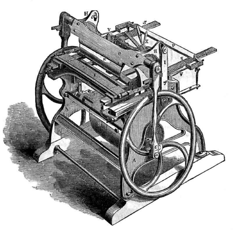
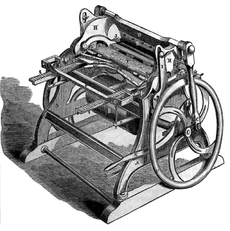
The annexed engravings are perspective views (figure 1 a view in front of the knives, and figure 2 a view behind the knives) of an improved machine for cutting and jointing staves, &c, invented by Charles Mowry, of Elbridge, N. Y., and for which a patent was granted in May 1849; since that time it has been improved in various particulars, as represented in the annexed figures. The assignees of the patent with the exception of New York State, are Messrs. Gwynnes & Sheffield, of Urbana, Ohio.
For this machine the logs are first sawn into plank about 4} inches thick, and then cut into bolts the desired length of the stave.— The bolt is softened by steam or warm water, then placed on the machine and cut and jointed while warm.
A A are the standards of the frame of the machine, and B represents a fast and loose pulley on the main shaft for driving the machine by a belt, and for setting it free when required; C is a connecting rod attached to the crank pin, a, and to the wrist, 4, of the knife stock, D; E is the cleaving knife. (There is a fly-wheel, connecting rod &c. on each side—the one a duplicate of the other.) The knife, E, receives a vibratory motion, and describes a vertical curve; d is the journal on which the arm, I, vibrates; c is a pin passing through a slot in the back of shoulders, H H, of the knife stock, D. The said shoulders are fixed on journals to allow the knife stock to vibrate, when the rod, C, moves up and down to raise the knife, E, and bring it down again upon the bolt of wood to be cut into stave, &c.; F and G are the two stocks of the jointing knives, the separate operations of cleaving the stave and jointing it being performed through the agency of the same connecting rods. The jointing knives have a horizontal motion, and are placed one above the other; the arms that move them receive a vibratory motion as follows; f, figure 1, is the pivot joint of the rod, J, belonging to the upper jointing knife, F. \8 the arm, 1, is moved through the agency of pin, c, working in the slot of shoulder H, as said arm vibrates, the rods, J J, are moved in towards and from the bolt to joint the stave.— The lower jointing knife, G, has the inner ends of its rod, N, hung on pivot joints in the sides of the frame, and the pin, O, (one on each side,) projects through the slot in the lower part of the arm, I. When the said arm is vibrated, the lower jointing knife will therefore receive the same motion as the upper one. These knives are made to cut the proper, taper; g g are rails on which the guides of knife, F, slide. We have thus described the motions of the cleaving and jointing knives. We will now explain the feeding operations. Reference especially made to figure 2. T' is the bolt of wood to be cut into staves. It is placed on four iron bars, running lengthwise of the machine. The feed carriage comes up behind the bolt and pushes it forward to the knives; T T are toothed clamps which have teeth that take into the ends of the bolt to hold it firm; U U are the levers that work these clamps. They are operated by the lever, W, which works the circle plate, to which the inner ends of levers, U U, are attached. The lever, X, is merely a wrench to screw the circle plate fast when the bolt is clamped ; S S are the two racks of the feed carriage, and arms V V, and pall P is the feeder. The arms, VV, are secured on vibrating heads, R R, (one on each side) secured on pivots in the sides of the frame, and they have pins projecting through curved slots in the shoulders, H H. When the shoulders, H H, vibrate, the pins at R, in the slots, are so acted upon as to move the arms, V V, back and forth, and thus make the broad pall, P, take int* the racks, S S, notch after notch, and push them forward one notch for every stave to be cut. The bolt to be cut into staves passes under a guide plate or swinging bridge behind knife, E, in figure 2. When the bolt of wood is all cut up, by bearing down on lever, Z, (letter turned) it throws up the pall, P, and allows the feed carriage to be moved back for a new bolt. The lever, Z, therefore regulates the feed motion.
The upper jointing knife can be raised so as to regulate its position for staves of different sizes. In figure 1 L is a bar in front which vibrates in bearings in the frame, and is attached to suspended arms, M M, which are jointed to the swinging frame in which the knife stock, F, is placed, and also the guide bridge behind the knives. The lever, K, fig. 2, is attached at one side to the bar, L, figure 1, and works it, therefore, by moving the lever to any desired point, up or down, the upper jointing knife is placed so as to set the knives for operation, for staves of different widths; e e are simply screws working in bars, and are employed to make the pall, P bite in the rack. The jointing knives act before the descending knife, E, and when they recede the said knife descends, cleaves out the stave, and it is then finished. The machine, although it may appear complicated, is really not so; a close attention to the figures and description will render its operations plain. It cuts and joints 100 staves in a minute. We have seen a number of staves which were finished in one of the machines, and we can speak in the highest terms of their neatness and finish. There are 20 of these machines in successful operation.
For further information see advertisement on our advertising page.
US Patent: 6,419 |
|
 1854 Gwynnes & Sheffield, Mowry's Stave Machine
 1854 Gwynnes & Sheffield, Mowry's Stave Machine
|
|