|
Title: |
1902 Article-Reading Ironworks Co., Ltd., Lenoir Gas Engine |
|
Source: |
Gas & Petroleum Engines, 1902, pg. 54 |
|
Insert Date: |
8/31/2013 9:33:05 PM |
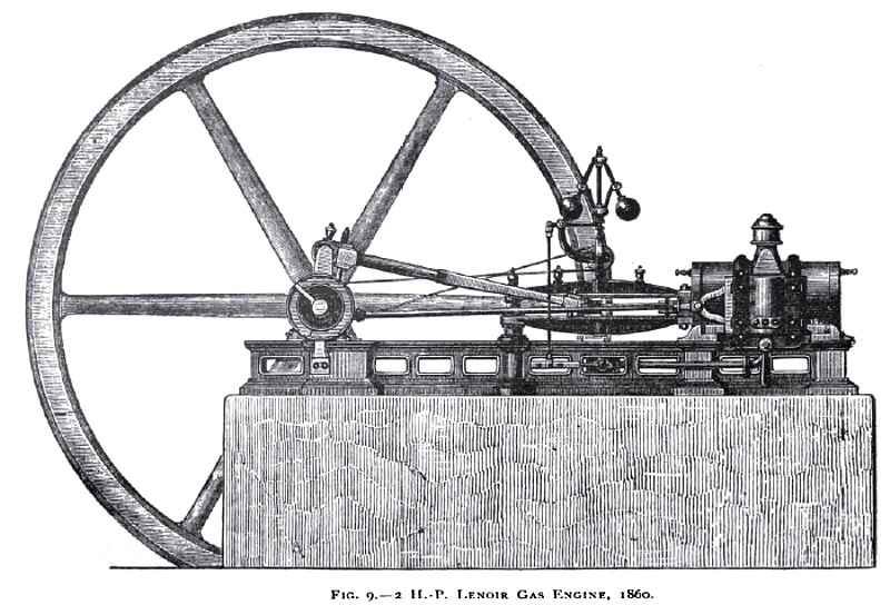
The Lenoir Engine (1860), Fig. 9, is horizontal and double-acting, like a steam engine. During the first part of each stroke the piston draws into the cylinder, at atmospheric pressure, the air and gas which mix in the admission valve port. Admission is cut off at about half stroke, and the explosive mixture closed up in the cylinder is ignited by the electric spark. The explosion causes a rapid rise of pressure in the expanding gases, and forces the piston to the end of the stroke. The pressure falls by the expansion of the gases doing work on the piston, and the cooling action of the cylinder walls. Near the end of the stroke the exhaust valve opens, and the products of the combustion are expelled during the return stroke. The energy stored up in the fly-wheel drives the piston forward during the suction part of each stroke, and the explosion during the remainder of it; at the same time expelling from the cylinder the burnt products of the previous explosion on the other side of the piston. This operation is repeated every stroke, and exhaust takes place exactly as in a double-acting steam engine.
The sectional plan Fig. 10, shows in diagrammatic form the general arrangement. The cylinder A, water-jacketed at every available point, contains the piston B working the connecting rod C and the crank-shaft F, connected thereto by the cross-head D and the fork E. The gas and air are admitted by the inlet slide valve G, and the products of combustion escape to the exhaust through the outlet slide valve H on the opposite side of the cylinder. These slide valves, are driven by separate eccentrics J and K on the crank-shaft, and work between the cylinder faces and covers held by screws against the valve faces.
Water circulates through the cylinder-jacket from a cooling tank or the water main, and sometimes by a small pump The gas supply pressure is kept steady by an india-rubber gas bag fixed on the supply pipe, as used with modern engines.
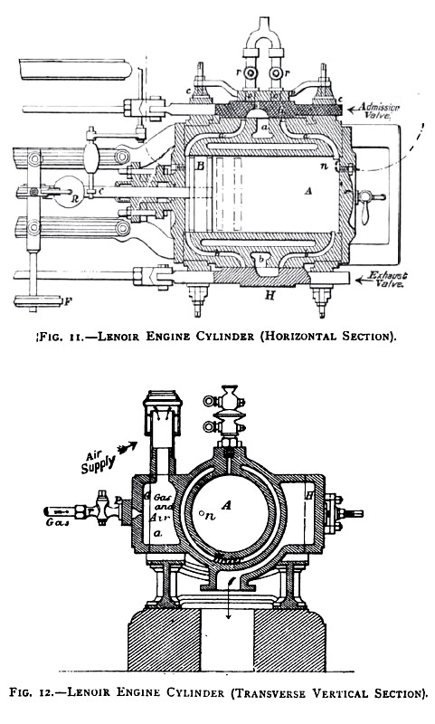
Fig. 11 is a partial plan, with a horizontal section, and Fig. 12 is a transverse vertical section of the Lenoir engine cylinder. The cylinder A, cast with the water-jacket, has two surfaced faces, upon which work the two slide valves G and H, which open and close alternately and at the proper time the admission ports a a for conducting the mixture of air and gas to each side of the piston, as well as the exhaust ports b b for the rejection of the products of combustion.
The slide valve G, which regulates the inlet of air and gas into the cylinder, is provided with one gas-admission port, which communicates with one or other of the two rows of holes b, c, Fig. 13, made in the brass plate. This plate carries the two cocks r, which admit the gas from the forked pipe. The air is admitted through the port a, which is made large to prevent throttling, and in communication with the open nozzle, surrounded by a cap, as shown in Figs. 11 and 12. The outlet slide H has only two slots, which are brought opposite the cylinder exhaust ports shortly before the end of the stroke, to allow the products of combustion to escape.
The inlet slide, Fig. 13, is of brass, grooved up at the ends, and pierced with round holes b, c, through which the gas enters the cylinder from the gas channels.
Fig. 14 is a cross section, taken through the line of holes opposite either of the two main ports in the cover, showing the larger rectangular passages for the admission of the air between the round gas ports. The gas and air are mixed thoroughly by thus entering the cylinder in numerous separate streams. This facilitates ignition by the electric spark between the ends of two wires at n Fig. 11. A battery of two Bunsen cells is used, with a Ruhmkorff induction coil and a commutator. The electric igniter n n placed at each end of the
cylinder, consists of a hollow brass plug screwed into the end covers of the cylinder, and having a porcelain or other suitable non-conductor in the form of a short rod fixed inside it. In this rod are placed the wires required to produce the spark; the one wire is in contact with the hollow metal plug, and the other is insulated by the porcelain in the plug, but in electric communication with one of a pair of small insulated plates or segments of a commutator. The positive pole of the battery is in connection with a third insulated segment, whilst the negative pole of the battery is in electric communication with the metal work of the engine. The electric circuit is closed by making contact with one or other of the pair of small insulated plates or segments and the third plate; this is done by a metal slide carried by the cross-head of the piston rod, kept in contact with both plates. The segments are adjusted so that the electric spark from the induction coil passes between the platinum points at either end of the cylinder, just as the gas admission valve closes at that end. When a short circuit occurs to cause a miss-fire or late ignition, the platinum points of the igniters must be cleaned and dried. This is a weak point, which gives trouble in practice.
The heavy fly-wheel drives the piston B forward from its position in Fig. 11, and draws in a charge of air and gas in the proportion of about nine to one. The air-port opens to the cylinder before the piston completes its previous stroke, and after that the gas port opens. The gas supply is regulated by a throttle valve and centrifugal governor R, Figs. 9 and 11, which alters the proportion of the mixture between six to one and twelve to one, so varying the rate and strength of the explosion until complete cut off. This proved very inefficient, as there was very little range to work on owing to want of compression, and the weak mixture gave late or retarded combustion or none at all, causing very irregular explosions. The inlet slide G closes when the piston has traveled about half the length of its stroke, causing the pressure behind the piston to fall slightly below that of the atmosphere. The mixture is then fired by a series of electric sparks; the pressure suddenly rises to about five atmospheres. The water-jacket has cooled the products of the previous combustion in the cylinder before the piston, and these are driven out, when the exhaust port H opens, at a pressure of about 1 • 5 atmosphere.
During the return stroke a mixture of air and gas is drawn in through G behind the piston, ignited at half stroke, and, as before, the burnt products on the other side of the piston are expelled into the exhaust at a temperature of 6oo° to 800° C.
In the half horse-power engine the temperature of the escaping gases is about 200° C. The engine is made to run from 45 to 130 revolutions per minute. The piston speed varies from 74 to 170 feet per minute. |
|
 1902 Reading Ironworks Co., Ltd., Lenoir Gas Engine
 1902 Reading Ironworks Co., Ltd., Lenoir Gas Engine (Top View)
 1902 Reading Ironworks Co., Ltd., Lenoir Gas Engine (Cylinder)
|
|