|
Title: |
1884 Article-Fielding and Platt, Hydraulic Riveting Machine |
|
Source: |
Scientific American, V 50 #1, 05 Jan 1884, pg. 8 |
|
Insert Date: |
8/14/2013 5:43:19 PM |
RAILWAY RIVETING MACHINE.
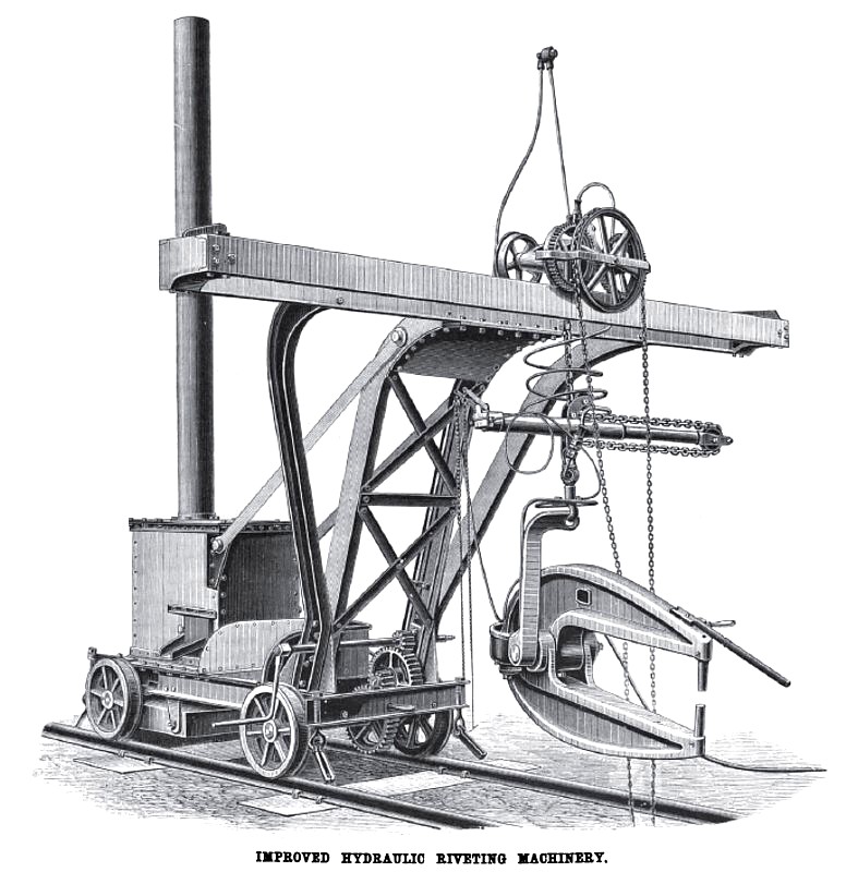
We illustrate a novel arrangement of a portable riveting machine and crane on Mr. Tweddell's well-known system.
The machine in question forms only a part of a very complete traveling plant, designed and manufactured by Messrs. Fielding and Platt, to the order of Mr. Arthur Sullivan, who is at present engaged in the construction and erection of some bridges on the Southern Mahratta Railway. The arrangement consists of a trolley or carriage, upon which is mounted a crane, carrying the riveting machine. By means of a cross gantry the latter is able to be moved in a transverse direction during the time the machine is engaged riveting. The trolley retires as the construction of the bridge progresses; the connection with the pressure main is never interrupted, as the flexible pipes and swivel joints allow for any change of position; a hydraulic chain lift adjusts the position of the machine vertically.
On the same trolley is also mounted a reverberatory rivet-heating furnace, which enables a considerable quantity of rivets to be always ready. The portable riveting machine, which is of the "Fielding " type, and has a gap of 42 In., is capable of closing rivets of 1 in. in diameter.
The riveting machine as shown is in proper position for riveting up the floor-plates of the bridges; it is, however, obvious that the machine can be used with a lever, vertically or horizontally, or at any intermediate angle.
In addition to the crane and riveter illustrated, a motive power trolley is supplied, on which is fixed the steam engine, boiler, accumulator, and pumps. Supplied from this same power trolley are also other travelers carrying spare riveters for different parts of the girders. The object of thus subdividing the plant is of course to minimize as much as possible the load to be carried by the girders during construction. |
|
 1884 Fielding and Platt, Hydraulic Riveting Machine
|
|