|
Title: |
1902 Article-Pierce-Crouch Engine Co., Brighton Gas Engine |
|
Source: |
The Gas Engine Magazine, V4 #1, Jan 1902, pg. 16-19 |
|
Insert Date: |
6/15/2013 12:49:56 PM |
The Pierce-Crouch Engine Company, of New Brighton, Pa., have sent us one of their new catalogues of the “Brighton Gas and Gasoline Engines,” which, as an example of catalogue making, we desire to commend. The illustrations really do illustrate and show the characteristic features of the engine in a way, which will prove instructive and acceptable to the prospective purchaser, and, being printed on highly calendared paper, show up very well. Except in the smaller sizes, the engines are horizontal and of the four-cycle type.
Their distinctive feature is the straight-line principle of construction first brought out by Prof. John E. Sweet, an ex-president of the American Society of Mechanical Engineers and the designer of the
Sweet Straight-Line Engine. This consists in securing the cylinder to the top of the bed by bolts through radial lugs on the cylinder, and connecting the cylinder to the crank-shaft bearings by two straight lines.
The bed has the appearance of being unusually strong and heavy, and is well designed for its work. The crank-shaft is of built-up construction, the crank pin and shafts being made of high-carbon open-hearth machinery steel, ground to size, and the cranks being cast-iron discs, which form the hubs for the fly-wheels. These are placed inside the bearings, and so permit of as nearly perfectly balancing the moving parts of the engine as is possible with a single cylinder reciprocating engine. The crank-pin and crank-shafts are hydraulically pressed into the cast-iron discs. The crank-shaft
bearings are parted horizontally and are lubricated by chain oilers. The crank-pin is lubricated by a sight-feed centrifugal oiler, as is now quite commonly the practice in high-speed engines. What would seem to be an unnecessary precaution to prevent the heating of the crank-pin and its brasses is the additional provision of a grease-cup on the connecting rod.
In the design of the cylinder provision is made for the removals of both cylinder heads so as to easily clean out any deposit of lime which may have formed in the jacket space. This is a point not infrequently overlooked by designers who are not familiar with the troubles incident to using hard water. The pistons are designed with ribs projecting inwardly, which not only strengthen the piston, but act as radiating surfaces. The strap form of connecting rod is used by this company, the rod being made of open-hearth steel and the boxes being made of phosphor bronze. No Babbitt metal is used on the engine.
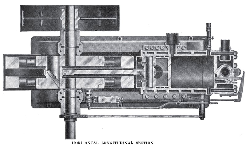
Referring to the illustrations of the valve mechanism, it will he seen that on the suction stroke gas and air are sucked in through the positively-opened poppet valves B and A and by the piston valve C. On the compression and expansion strokes the valve A is closed and the combustion chamber has the minimum of superficial area for its volume as a ?at-ended cylinder. At the end of the expansion stroke the products of combustion are exhausted through the auxiliary port, and the remainder of the burnt gases are passed out through the valve A and by the upper end of the piston valve C to the exhaust pipe. At the end of the exhaust stroke the lever F causes the valve C to close the exhaust valve and at the same time open the inlet mixing valve at its other end. By this means one valve is made to perform the duty of two valves and being positively operated in both directions by a crank motion, a number of springs and other parts are dispensed with.
Governors of the hit-or-miss type are used on engines of six horsepower and smaller, and either throttling or hit-or-miss governors are used with the larger engines, as may be desired for the work to be done.
The shaft governor as used on these engines consists of a disc carrying a lever attached to it at the fulcrum by a strip of spring steel, thereby doing away with journal friction, the necessity for lubrication and the possible lost motion at this point. With the throttling governor, both the air and gas inlets are under the control of the governor.
With the engines above six horsepower ignition is provided by both the incandescent tube and the electric spark. The smaller engines are equipped with incandescent tube igniter only, which is of a very simple and direct form and without any timing mechanism. The igniter points for the electric ignition are said to be made of iridium, which is even harder than platinum and has a higher fusing point. We question the advisability of using pure iridium for the igniter points on account of its brittleness and extra cost as compared with a platinum alloy containing 7 to 10 percent of iridium.
The engines are started by using either a detachable crank applied to the shaft or an automatic starting attachment consisting of a gasoline cup and a compressed-air tank. This tank is charged by shutting off the gas supply, opening the sealing valve and raising the starting valve, whereby the energy stored in- the fly-wheels recharges the air tank to the desired pressure. No auxiliary air compressor is required or used.
Special attention is said to be paid to the testing of each engine. After having been tested at part and full loads for several days, it is dismantled and inspected for defects, which the tests may have developed. If it passes this final inspection it is reassembled, again tested, painted and prepared for shipment. By this thoroughness of inspection and testing, subsequent troubles are in large part prevented.
The driving pulley is usually put on the right-hand side of the engine; and, on account of the position of the fly-wheels inside the main bearing, it can be put close up to the bearing and not be overhung as much as is ordinarily necessary. Any style of pulley may be used, as it is not fastened to the fly-wheel. A sheet-metal shield over the fly-wheels acts both as an oil shield and as a guard against contact with the rotating fly-wheels.
When used for the generation of electricity, the dynamo may be either belted to the engine, as is customary, or the shafts may be direct connected by flange coupling and without the use of a flexible connection. The dynamo is then bolted to a sub base, which in turn is bolted to the engine bed. as well as to the foundation. On account of the absence of a fly-wheel between the generator and the crank-shaft bearing in the bed, only one outboard bearing for the generator is required. It is even possible to mount the armature on the extended crank-shaft of the engine. In any case, the installation is very compact and entirely self-contained.
We believe that the Pierce-Crouch Company will find this catalogue to be very helpful in making business for them, and that its readers will appreciate their efforts to make their engine intelligible and clearly understood by persons interested. |
|
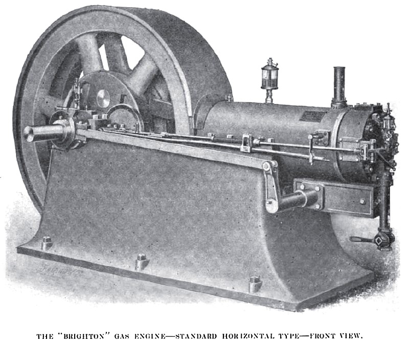 1902 Pierce-Crouch Engine Co., Brighton Gas Engine
 1902 Pierce-Crouch Engine Co., Brighton Gas Engine (Top Cut-Away View)
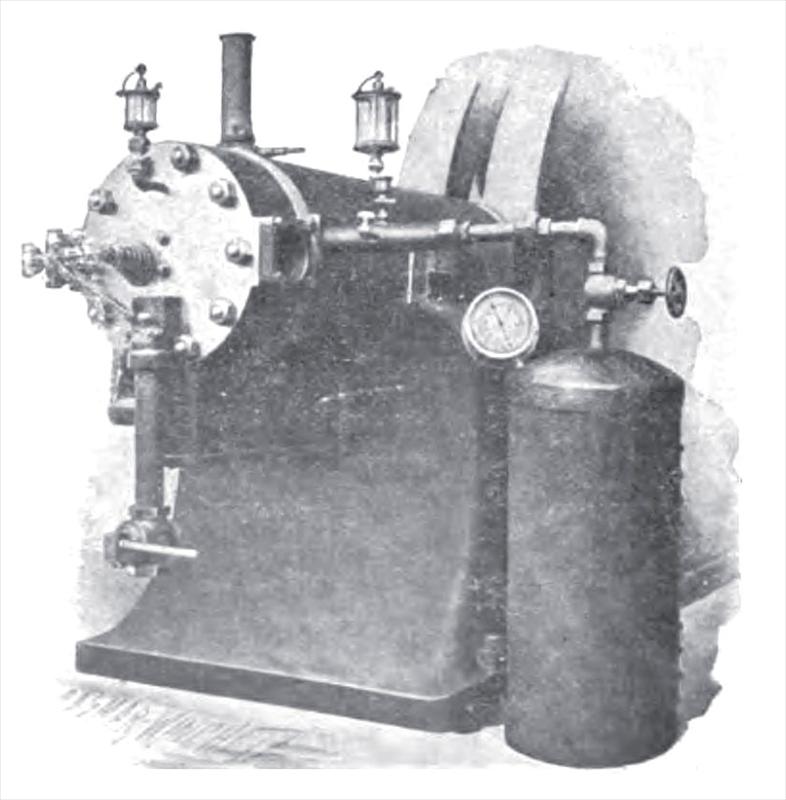 1902 Pierce-Crouch Engine Co., Brighton Gas Engine with Starting Attachment & Storage Tank
|
|