|
Title: |
1926 Article-Blanchard Machine Co., Vertical Surface Grinder (Part 1) |
|
Source: |
The Engineer Magazine, 02 Jul 1926 pg. 16 |
|
Insert Date: |
6/13/2013 8:09:24 PM |
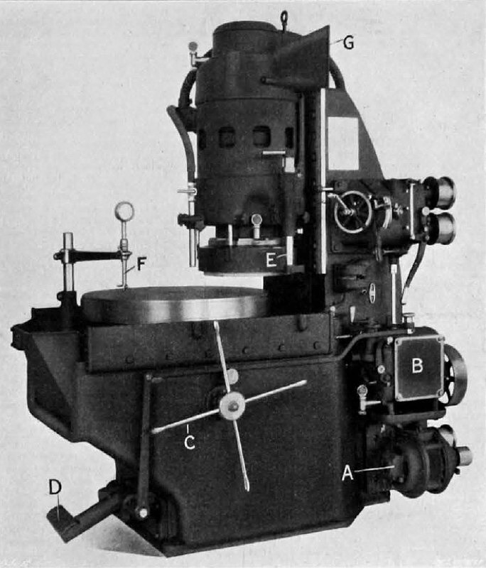
The high-power vertical surface grinder made by the Blanchard Machine Company, of Cambridge, Mass. U.S.A., and illustrated herewith, is already fairly familiar in this country. Recently, however, the wheel head embodying the 25 horse-power induction motor which drives direct on to the wheel spindle has been redesigned and simplified, and it in with it that we are now mainly concerned. A brief general description of the machine may, however, prove of interest.
The work is supported on a 26in. magnetic chuck taking a little over one-third of a kilowatt, direct current.
To load the chunk with work the sliding carriage on which it is mounted is pulled outwards. This movement automatically opens the water guards surrounding the chuck. These guards are not shown in our engraving of the machine. The chuck when loaded in returned inwards until its centre is approximately below the foremost point on the periphery of the grinding wheel.
A 2 horse-power motor A, Fig. L, and a change gear-box B drive the chuck at any one of six speeds ranging from 5 to 28 revolutions per minute. The grinding; wheel runs at 900 revolutions per minute. Hand
or power feed in the downward direction can be applied to the wheel head as a whole, the power feed ranging from 0.0002in. to 0.0005iin. per revolution of the chuck by steps of 0.0002in. Rapid power motion is provided for raising and lowering the head when it is necessary to change to work of a new height. The horizontal movement of the chuck carriage is not employed to feed the work beneath the wheel but simply to facilitate loading. This movement is effected by the star handle C. A treadle D enables the chuck to be rotated during the loading period.
At E is shown a wheel dresser, which can be operated, if desired, while the wheel is actually grinding. The wheel is 18in. in diameter and 5in. deep, and is provided with a wire banding to prevent breakage. The wire bands are stripped off as the wheel wears.
A continuously reading caliper gauge F, set to ride over the work, enables the operator, at any instant, to see at a glance how much material remains to be removed.
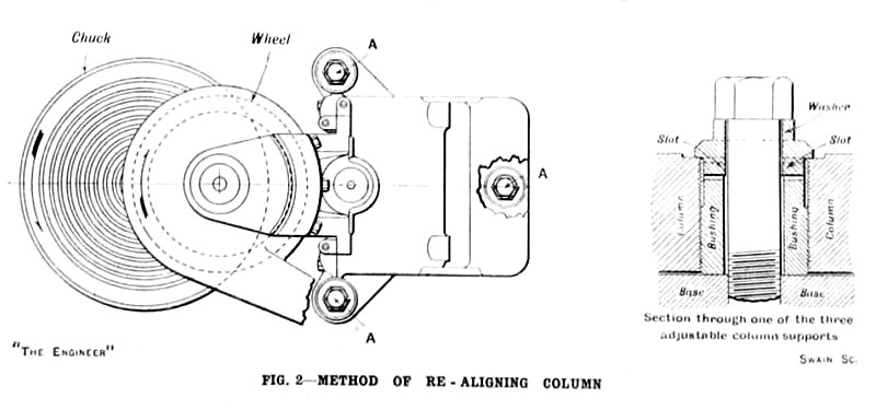
Should the bearings and slides wear so as to cause the spindle to loose its squareness with the chuck, the column can quickly be re-aligned by the aid of a spanner. The column, as shown in Fig. 2, is bolted to the base at three points, A. Screwed bushings surround the bolts and can be made to lift or lower the column through the agency of washers provided with projections on their undersides to engage slots in the tops of the bushings.
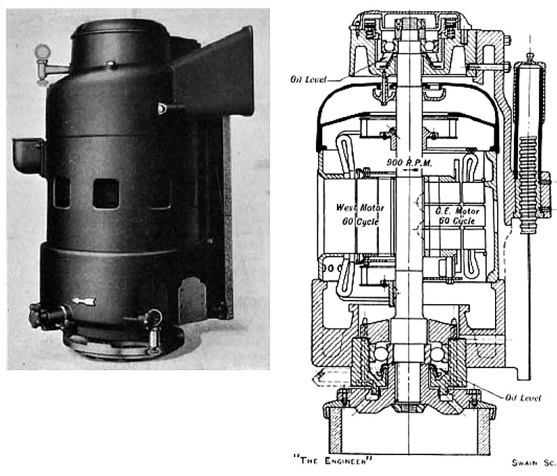
The wheel head is illustrated in Figs. 3 and 4, and in Fig. 5 the spindle is shown separately. The motor, either a Westinghouse or a General Electric machine, is built round the spindle. Above and below the motor armature the spindle carries fans, which ventilate the motor by drawing in air through the duct. G, Fig. 1. and delivering it through openings in the side of the head casing. Two large ball bearings of the radial thrust type support the weight of the spindle and its attachments. The top ball bearing is held up by springs which take up all end play and, in addition, throw at all times a considerable upward thrust load on to the lower or main bearing. This lower bearing contains 11 balls, 1 5/8in. in diameter. In the earlier design of the machine, the spindle was carried in four bearings, namely, two thrust and one radial ball bearings and a bronze bushing. The wheel is set in sulfur or cement in a cast iron ring, which is attached by six bolts to the face-plate on the spindle. A guard surrounds the wheel and is attached directly to the head and not to a
spider casting, as was formerly the case. In the base of the machine a tank is formed for the reception: of the cooling medium. From this tank a pump driven by the 2 horsepower chuck motor delivers the liquid on to the work through a nozzle fixed against the outside of the head casing. In addition. the liquid in also delivered into the interior of the grinding wheel by way of a passage leading downwards and outwards from behind the spindle face-plate to the front. The swarf returning with the cooling medium to the tank in the base is removed therefrom by moans of n hoe, the tank, to facilitate this cleaning process being formed with a sloping wall at the front.
The Engineer magazine courtesy of Grace's Guide
http://www.gracesguide.co.uk/The_Engineer_1926/07/02 |
|
 1926 Article-Blanchard Machine Co., Vertical Surface Grinder
 1926 Article-Blanchard Machine Co., Vertical Surface Grinder Column
 1926 Article-Blanchard Machine Co., Vertical Surface Grinder Head
|
|