|
Title: |
1893 Article-John Fowler & Co., Spring Steam Traction Engine |
|
Source: |
The Engineer Magazine, 23 Jun 1893 pg. 538 |
|
Insert Date: |
3/19/2013 7:11:56 PM |
Messrs. J. Fowler & Company, of Leeds, make a large display of engines, but the novelty at their stand is their new spring gear. It is not easy to make the construction and action of the gear intelligible, even with the section of the engine which we publish. The main road axle and the counter-shaft are kept at a uniform distance apart by two links, one at each end, connecting the bearings. The bearings have room to rise and fall a couple of inches in angle iron guides. The pinion on the counter-shaft is always in proper gear
with the spur wheel on the driving axle, since both must rise and fall simultaneously. The pinion on the crank shaft drives a spur wheel, which is usually mounted on the counter-shaft. In this case, however, it is mounted on a hollow stud or " cannon," bolted to the side frames. Through this cannon passes the circular shaft without touching it, the bore of the cannon being considerably greater than the diameter of the counter-shaft. In order to couple the spur wheel with the counter-shaft pinion a very ingenious device is used. A circular steel plate is interposed between the pinion and the spur wheel: This at the two extremities of a diameter has projections, which go into two slots in the pinion. At the two extremities of another diameter, at right angles to the first, it has two slots into which enter projections on the spur counter-shaft wheel. In this way the pinion may be eccentric to the spur wheel to the extent of an inch or more, but the one revolving will drag the other round with it. The action is very similar to that of gimbals in one sense, and in practice the gear is found, we understand, to work very well. Time, however, can alone show whether it is or is not possible to make the wearing surfaces in the clutch sufficiently large and hard to avoid somewhat rapid dissolution; so far, however, the results obtained seem to be all that are claimed. The range of motion in the springs is but small, about one inch being found sufficient. There are two bearing springs side by side, which carry eight tons between them. The compensating levers shown in the section secure the absolute parallelism of rise and fall at both ends of the shafts. Messrs. Fowler thus state the advantages which the claim:— “(1) The power is transmitted by a driving plate having large bearing surfaces and long leverage, thus avoiding wear and back-lash. (2) The pitch circles of the driving gear are always rolling truly together, thus insuring smooth running. (3) The bearings are coupled by compensating levers giving a vertical parallel motion, consequently there is no oscillation of the gear wheels or wear on the teeth therefrom. (4) Adjustment of the main springs by compensating levers and one central screw and nut, giving equal elasticity on both sides of the engine, and keeping all the parts in tension, obviating any knocking of joints. (5) The pulling strain on the drag bar is taken direct by the horn blocks, and does not affect the spring gear in any way. (6) This arrangement gives a minimum of wear and tear throughout the entire engine, and avoids jar and vibration on the roads. (7) The spring fore-carriage allows a free movement of the front wheels in every direction, and gives a. uniform strain on each end of the spring.”
Image courtesy of Grace's Guide.
http://www.gracesguide.co.uk/images/0/09/Er18930623.pdf |
|
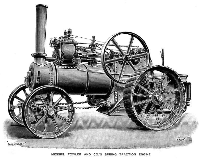 1893 John Fowler & Co., Spring Steam Traction Engine
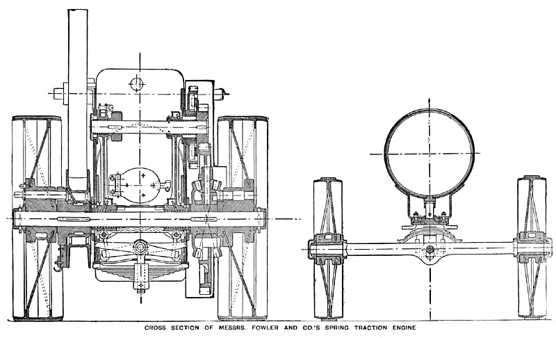 1893 John Fowler & Co., Spring Steam Traction Engine Cross Section
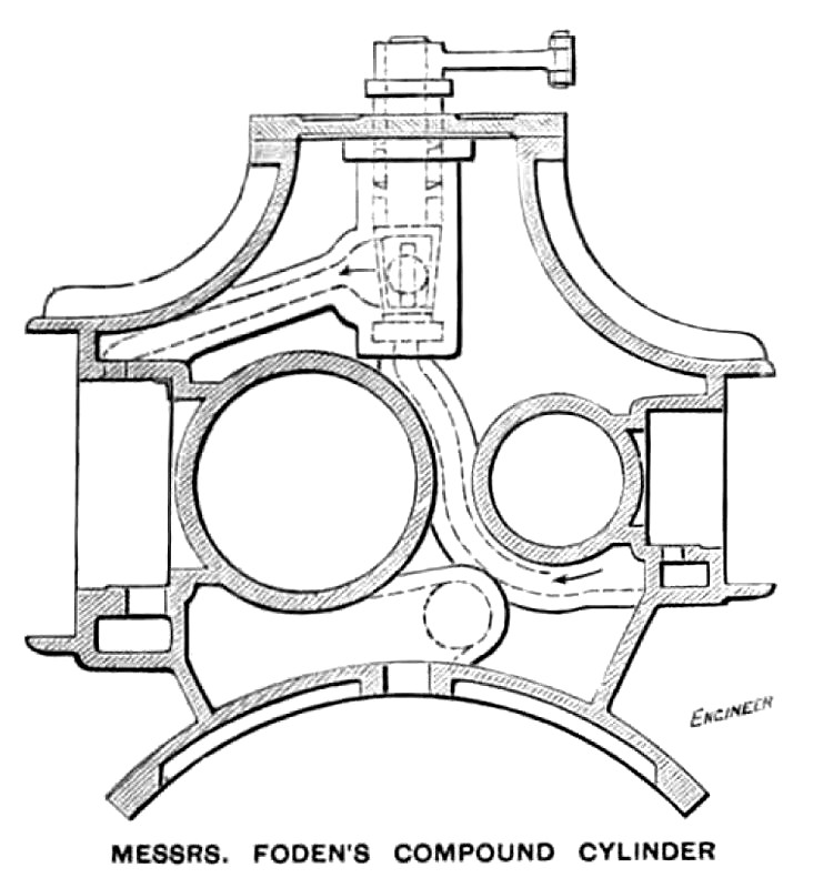 1893 John Fowler & Co., Spring Steam Traction Engine Compound Cylinder
|
|