Image
|
Title: |
1872 Article-New York Steam Engine Works, Wilder's Patent Punching & Shearing Machine |
|
Source: |
Scientific American, V 27 #12, 21 Sep 1872, pgs. 175 & 176 |
|
Insert Date: |
3/12/2013 2:14:37 PM |
PATENT PUNCH AND SHEARING MACHINE
Perhaps in no branch of metalworking has there been greater progress than is shown m the manufacture of all descriptions of punched and stamped ware. There are, in fact, but few of the myriad of metal articles found upon the shelves of our hardware and house-furnishing stores which are not, in some stage of their manufacture, subjected to the action of a machine of this class. That high degree of skill which was necessary to produce each article is now made available through these machines, in producing a thousand articles precisely alike, and at a price very low in comparison with former times, when such work was done by hand.
Our illustrations represent three forms of machines made under patents granted to Moses G. Wilder, bearing date June 27, 1871, and May 28, 1867 (re-issued June 27, 1871.)
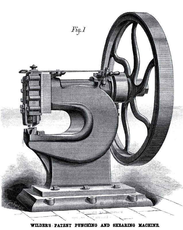
Fig. 1 is known as Wilder's patent combined punching and shearing machine. This apparatus is made to punch holes three fourths of an inch in diameter, in iron one half inch thick, to the center of a forty inch sheet, and will shear half inch iron to the center of a thirty-six inch sheet. It is constructed in two forms, one with a plain fly wheel of large size, as shown in the engraving, for use where a somewhat rapid motion is possible. The other, with a geared driving train, permits a slower motion of the punch and increases the power of the machine, so that, when geared, it will punch three fourths inch holes in three fourths inch iron, and will shear three fourths inch plates or bars. The engraving shows both the punch and shear blades in position though this is never the case when the machine is in use. The punch and upper shear blade are so arranged that either may be removed instantly or replaced with perfect certainty. The die and lower shear blade remain fixed at all times, except when it is necessary to change the size of the holes to be punched or to sharpen the shears.
Among the advantages claimed for this machine are that its form is such that it may be set back against a wall or partition, instead of in the center of the shop floor, as is now the case with the ordinary combined punch and shears owing to the peculiar manner of combining the punch and shears in one pair of jaws, instead of making the machine double, it can be sold at a low price, while it has every capacity for work. The machine may be run continuously or arrested after each movement, or may be arranged to stop at any point in the revolution. The distribution of metal is such that the machine is rigid and still, and does not spring perceptibly in doing its heaviest work.
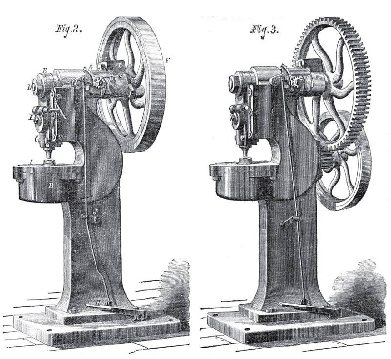
In Fig. 2 is shown another form of these machines, such as is used for punching sheet metal into the great variety of shapes required by brass and hardware manufacturers, silversmiths, tinners, etc., in cases where rapidity of movement is of more importance than great power. The die is held in any suitable manner upon the bolster plate, A. This, in its turn, is fastened by bolts to the die bed, B. The punch is held in the lower part of the slide or gate, C, in such manner as that, when the slide descends, it will enter the die, cutting out a piece from any material previously interposed between it and the die, and of the precise form of the latter. Motion is given to the slide, C, by an eccentric or crank wrist on the front end of the shaft, D, through a pitman or connection, E, which is pivoted at its lower end to the slide, C, and which, at its upper end, surrounds the crank, D. The shaft, D, receives motion from the flywheel, F, which runs loosely upon it and is connected to it by the sliding bolt of the stop motion, G, when the treadle, H, is depressed by the foot of the operator. This sliding bolt is so formed that-,when the press is at rest, the pressure of the operator's foot forces it into engagement with the wheel positively. As the press starts, this bolt, which is fitted to slide back and forward in an arm or reinforce, I (which is keyed rigidly to the shaft, D, and revolves with the shaft), also revolves with the wheel and shaft. The stop bolt is moved back and forward by means of a sliding cam plate, which is fitted to the frame of the machine at G. This cam plate has a channel way with inclined faces through which the stop bolt passes in each revolution. These inclined faces act upon the bolt to move it in or out, and are governed by the treadle worked by the operator. The cam plate is connected to the treadle by means of an eccentric gear working upon a fixed stud placed in the side of the frame, a toothed sector, which acts upon the gear and a small rod to connect this sector to the treadle, H. Inside of the frame is a counter-weight which acts upon the treadle rod, at J, to lift the treadle, H, when the operator’s foot is removed. When the treadle is depressed, the press starts and will continue running while the treadle remains down. When the foot is removed, the weight at J operates to move the cam plate back from the arm, I. The stop bolt, as it enters the channel way in the cam plate, is withdrawn, releasing the wheel F, and the press stops, remaining at rest until the treadle is again depressed. The parts of this stop motion are strong and simple in form and work wholly without springs.
The pitman, E, is pivoted to the slide, C, at its lower end by an eccentric wrist pin, K. This wrist pin revolves in bearings in the slide, C, and forms the fulcrum for the pit» man through which the latter moves the slide. Where surrounded by the pitman the wrist pin is eccentric to its journals. When the wrist pin is revolved, it changes the height of the pivot or fulcrum relative to the punch, and thus not only varies the distance to which the punch is depressed in working, but also compensates for the wear of the latter and of the die. The front end of this wrist-pin is enlarged, and is made with a toothed periphery as a worm gear, and is so arranged that, by turning the worm which is carried in journals formed upon the slide, C, the punch may be raised or lowered to any desired extent.
Fig. 3 shows a geared press of the same size and description as that shown in Fig. 2, but having a geared train such as would be used where the rapid motion of the plain flywheel would be objectionable.
These presses are now made in a large variety of forms, adapted to all kinds of work, by the New York Steam Engine Company, 121 Chambers Street, New York, to whom application should be made for further information. |
|
 1872 New York Steam Engine Works, Wilder's Patent Punching & Shearing Machine
 1872 New York Steam Engine Works, Wilder's Patent Punching & Shearing Machines
|
|
|
|