|
Title: |
1872 Article-Holt & Hawkins, Hawkins' Spool Blank Roughing Machine |
|
Source: |
Scientific American, V 27 #10, 07 Sep 1872, pg. 143 |
|
Insert Date: |
3/5/2017 5:29:52 PM |
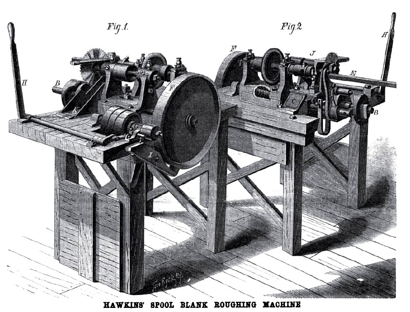
HAWKINS’ SPOOL BLANK ROUGHING MACHINE
Our engraving illustrates a new and improved machine for making spool blanks, round wood boxes, and other similar articles. Fig. 1 is a perspective view taken from the rear of the machine, and Fig. 2 gives a front view of the same. The improvements consist in the following additions to the regular cutting and sawing apparatus which constitutes the ordinary spool blank rougher: namely, the reciprocating shaft, A. the rotating shaft, B, and the standard, C, with their various attachments.
The shaft, A, can either rotate or slide longitudinally in its bearings, and carries an upwardly projecting arm, D, to which is attached the V shaped carrier, E. In this carrier, which is adjustable to varying sizes of wood, is laid the square stick to be operated upon. A bent lever is pivoted to the arm, D, above the carrier, as shown in the engraving, and is actuated by a. spring in such a manner as to firmly hold, by means of an adjustable clamp at its end, the square stick in the carrier while it is being cut, bored, turned, or sawn ofl‘. On a. stud projecting horizontally from the end of the shaft, A, is placed a roller which engages with the cam seen in the end of the shaft, B; and on a stud projecting from the arm, D, is placed a roller which engages with an inner cam on the shaft, B, as shown. The effect of the first cam is to move the shaft, A, and carrier, E, inward during a portion of the revolution of B, and of the second to rotate the shaft, A, and to press back and hold in the requisite positions the arm, D, and the carrier. A helical spring surrounds the shaft, A, as shown through the part broken away in Fig. 2, and is attached by one end to the shaft, and by the other to a fixed part of the machine. It is thus made, by its recoil, to return the shaft and the carrier to their original positions after they are released by the cams.
The standard, C, carries a stop, against which the bent lever of the arm, D, is made to strike by the action of the inner cam, so as to compress the spring and release the stick at the moment when it requires shifting in the carrier. The shaft, B, carries upon its rear end the friction pulley, F, and is driven by the friction pinion attached to the shaft, G. This shaft runs in movable bearings, and the friction pulleys are made to engage or disengage at the will of the operator by means of the toggle joint, shaft, and handle, H, shown distinctly in Fig. 1. At I is a friction brake, by means of which, in disengaging the friction pulleys, the pulley, F, is brought to rest at any point, and as quickly as desired.
In the operation of the machine, the outer cam of the shaft, B, moves the arm, D, inward, forces the stick into the cutter head, and afterwards releases it therefrom; at which time a depression in the inner cam allows the spring to throw the arm, D, to the right and carry the stick to the saw to have the finished piece cut off. After this is done, the further rotation of the inner cam throws the arm, D, to the left and brings its lever in contact with the stop on standard, C, as before described, and releases the stick. The stick is then advanced in the carrier by the operator, according to the nature of the work; the arm falls into its central position opposite the cutter head; the clamp again grasps the stick, and the operation goes on as before. A rest, J, the operating parts of which are not shown in the engravings, is provided to support and guide the stick to the cutter after it has become too short to lie unbalanced in the carrier. An inverted rest is attached near the saw, as shown, by which the workman cuts out imperfect pats of the lumber. K is a chute by which the finished pieces are conveyed to a receptacle below.
The mechanism described can be applied, the inventor states, to any of the ordinary spool blank roughers at a moderate expense; it saves, he estimates, not less than two thirds the cost of the old manufacture. It is adjustable in every way required to make articles of various lengths and diameters, and besides spool blanks and boxes, any cylindrical goods may be made by it which are sufficiently well finished by the saw at the ends. Among the advantages claimed for it are: the correctness with which it does its work; its ability of using up lumber of any length to within a very short distance from the end—say, one quarter inch—and also of making perfect work from crooked lumber. It can be run by a boy. The machines, as made, are geared for different speeds, and produce from 150 to 175 gross of spool blanks per day. They are in operation at the spool manufactory of Holt & Hawkins, Salisbury, Vt., who may be addressed for further information on the subject. Application for a patent is pending in the name of John T. Hawkins.
Patent #87,929
http://datamp.org/patents/displayPatent.php?number=87929&typeCode=0 |
|
 1872 Holt & Hawkins, Hawkins' Spool Blank Roughing Machine
|
|