|
Title: |
1872 Article-Greenwich Machine Works, Weaver's Sawing, Boring & Planing Machine |
|
Source: |
Scientific American, V 26 #26, 22 Jun 1872, pg. 414 |
|
Insert Date: |
11/18/2017 5:24:26 PM |
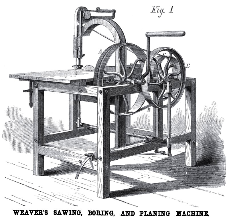
Sawing, Boring, and Planing Machine.
The invention we illustrate supplies workers in wood with a useful machine that can be readily adjusted for service either as a scroll saw, a circular saw, a planer, or a boring machine, and which may be run by hand or by power, as desired. Its most important feature is a skillful and effective contrivance by which the speed is multiplied and the power conveyed from the driver to the tool.
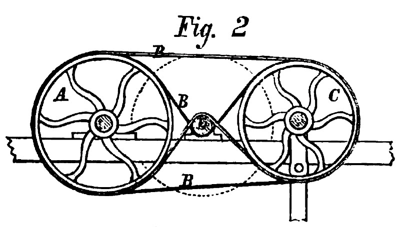
The machine is represented in Fig. 1, and Fig. 2 shows, in detail, the peculiar arrangements of pulleys and belting for conveying the power, etc. A is the driving pulley or drum. B are belts which pass around it, and around the loose pulleys, C. These belts are drawn inward, on opposite sides, as shown in Fig, 2, so as to surround the shaft or small pulley, D, and communicate motion to the same. The loose pulleys, C, run on a shaft attached to the upper ends of two levers, one of which is partly shown in Fig. 2; the lower ends of the levers are connected by a crossbar, to which is attached a strap that admits of being secured to the frame of the machine, as shown in Fig. 1. By this arrangement the tension of the belts is adjusted. The shaft, D, extends across the frame, and carries at its outer end the fly wheel, E; this is attached by a pin to a connecting rod which gives motion through a crank to the rock shaft, F, the crank being adjusted so that the revolution of the fly wheel only rocks the shaft. This motion of the rock-shaft is conveyed through slides to the scroll saw, causing it to make its downward stroke; the recoil is secured by the band, pulleys, and spiral spring seen at the top of the machine.
To the shaft, D, may be attached a circular saw in the ordinary manner, and to its inner end (not shown in the engraving) a cutter head, suitable for light planing or molding, or a boring tool, may he affixed. The table is provided with gages, and is adjustable to any elevation required by the character of the work. Our engraving shows both scroll and circular saw attached to the machine, but, in practice, when the scroll saw is used, all the other tools should he detached from the shaft; and when either circular saw, planer, or boring tool is employed, the crank pin of the fly wheel should be detached from the connecting rod, and the operation of the scroll saw prevented. The position of the belts on the pulley or shaft, D, puts equal pressures on opposite sides of the same, and does away with all side strain. Almost the entire periphery of the shaft is in contact with the belts, and a very large surface contact, as compared with the size of the shaft, is obtained. This, and the absence or the used intermediate belts and pulleys employed for attaining speed, insure the utilization of the power applied and prevent its waste. We are informed that the hand power machine has been employed to saw three-inch hard oak felloes and other carriage work with perfect success.
It is manufactured extensively by the Greenwich Mowing Machine Company, of Greenwich, N. Y., of whom further information may be obtained. Patented through the Scientific American Patent Agency for the inventor, Mr. William Weaver, October 3rd, 1871, and January 30, 1875.
Patent #'s 119,674 & 123,211.
http://datamp.org/patents/displayPatent.php?number=119674&typeCode=0
http://datamp.org/patents/displayPatent.php?number=123211&typeCode=0 |
|
 1872 Greenwich Machine Works, Weaver's Sawing, Boring & Planing Machine
 1872 Greenwich Machine Works, Weaver's Sawing, Boring & Planing Machine Pulley System
|
|