|
Title: |
1872 Article-Providence Steam Engine Co., Greene Steam Engine Valves |
|
Source: |
Scientific American, V 26 #20, 26 May 1872, pg. 302-303 |
|
Insert Date: |
10/13/2018 1:26:28 PM |
THE GREENE ENGINE
The cut-off patented by Noble T. Greene has been favorably known for many years, its simplicity and durability, its economy and sensitive regularity ranking it among those improvements which are conceded to represent the highest state of the art. In March, 1869, the patent was extended and passed into the possession of the Providence Steam Engine Co., who, it is stated, are now able to build the engines fast enough to supply the demand.
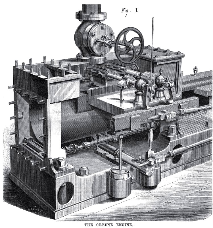
The following improvements have been made: A new bed plate has been designed; access is had to the exhaust valves by removing the cylinder heads, as shown in Fig. 1; an intermittent movement allows these valves to remain at rest through nearly seven eighths of the stroke, and the mechanism actuating both steam and exhaust valves is now placed outside of the steam chest. The principle of the original Greene engine is not changed, but the parts retained, after reconstruction, are more durable, have larger bearing surfaces, and are made easy of access to the engineer.
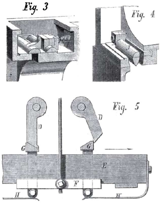
The engine is of that class which does not require a throttle valve. The steam enters the cylinder at boiler pressure, and the governor fixes the period of time during which the steam valves shall remain open, allowing more or less steam to flow into the cylinder as there is more or less load to be driven. There are four flat slide valves, one (as shown in Fig. 3) at each end on the top to let in the steam, and one (as shown in Fig. 4) at each end on the bottom to let out the exhaust, and with as little clearance as the thickness of metal in the cylinder will allow.
While one valve is admitting and cutting off the steam, the other three are entirely at rest until just before the completion of the stroke, when the exhaust valves instantly rearrange themselves, opening the exhaust on one side of the piston and closing it on the other. The return stroke then commences, and the operation is repeated.
The short space of time during which the exhaust valves are moving is when the pressure upon them is the least, and, by an arrangement of cushioning the steam, the induction valve is at all times nearly balanced.
The power which moves the valves is applied parallel to, and nearly in line with, their seats, so that they cannot rock or twist, thus greatly reducing any tendency to wear. One end of each valve stem being in the steam chest, the whole boiler pressure acts upon it to aid the weight in closing the valve when tripped, and the valve stem is made large in diameter to obtain the full benefit derived from cut-off valves closed by steam pressure. The governor can adjust the point of cut-off over a range of three-fourths the entire stroke.
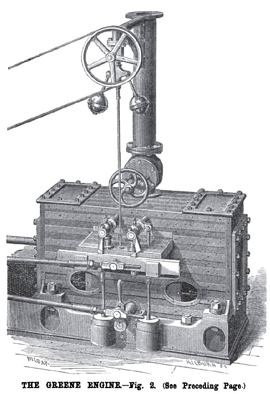
The working of the valve gear will be understood by reference to the engravings. Figs. 1 and 2 are perspective views of the cylinder and valve gear, Fig. 1 having certain parts removed. Figs. 3, 4, and 5 are sectional details.
The induction valves, Fig. 3, are connected with the rock lever shafts, A, Fig. 1, arms, B, working in slots in the valve stems, C. Below the rock levers, D, is a sliding bar, E, receiving a reciprocating motion from an eccentric on the main shaft. Behind the sliding bar is a gags bar, F, Fig. 5, connected with the governor, which bar receives an up and down motion from a corresponding movement of the governor balls. The adjustable tappets, G, Fig. 5, in the sliding bar, are kept up in contact with the gage bar, F, and are made to move up and down in unison with it by the springs, H, Figs. 1 and 5.
It will be seen from this description that, as the sliding bar moves in the direction of the arrow, Fig. 5, one of the tappets is brought in contact with the inner face of the toe on the rock lever, causing it to turn on its axis, thereby opening the steam valve at one end of the cylinder, the other tappet meanwhile passing under the other rock lever without moving it, the toe and tappet being so beveled that the tappet will be forced down against the action of this spring until it has passed by the toe, when the spring causes it to fly up to its original position, ready to open the induction valve at the opposite end As a result of this motion, the two tappets always open the steam valves at the same period, but, the tappets moving in a straight line while the toe describes the arc of a circle, the tappet will pass by, liberating the toe. which is brought back to its original position by a weight, I, Fig. 2, and the steam pressure on the valve stem, thus closing the valve and cutting oil" the steam. This liberation will take place sooner or later, according to the elevation of the tappets; that is, the lower the tappets are, the sooner the toes will be liberated, and vice-versa; and so, by simply elevating or depressing the gage bar, F, Fig. 5, the period of closing the valves can be changed, while the period of opening them remains the same. The adjustment of the gage bar is effected by the governor, and the steam is cut off sooner or later according to the amount of load.
The exhaust valves, J, Figs. 1 and 4, which lie in the bottom of the cylinder, are connected at their outer ends by parallel rods, K, which are tied together by a crossbar in the inside.
The exhaust rock-shaft arm, L, is it jaw, as shown in Fig, 1, just under the cylinder. One side of this jaw comes in contact, with a lug, M, on the crossbar, and moves both the exhaust valves simultaneously, W opening one and closing the other. While the exhaust eccentric is taking up the lost motion, between the sides of the jaw, the exhaust valves remain at rest. The other side of the jaw coming in contact with the crossbar, the exhaust valves receive a reverse motion. The lug on the crossbar is so shaped that it receives no blow from the jaw, L, but takes a gradually accelerated motion.
The strength, simplicity, and durability of this engine is very noticeable, and it embodies all the advanced
views in stationary engineering which have stood the test of actual practice.
Its finish is also neat and tasty, and, with the improvements described, it thus embodies all the essentials necessary to extend the wide popularity the original engine enjoyed.
In these days of active competition, any marked improvement upon the construction of a steam engine is of importance, not only to purchasers, but to manufacturers. As the use of steam expansively is now well nigh universal, the value of a variable cut-off that combines in so great a degree as this does, delicacy of action with strength and durability, is sufficiently obvious.
For circulars and other information, address Providence Steam Engine Company, Providence, R. I. |
|
 1872 Providence Steam Engine Co., Greene Steam Engine Valves
 1872 Providence Steam Engine Co., Greene Steam Engine Valves
 1872 Providence Steam Engine Co., Greene Steam Engine Valves
|
|