|
Title: |
1872 Article-Lemuel R. Palmer, Stave Jointing Machine |
|
Source: |
Scientific American, V 26 #15, 06 Apr 1872, pg. 226 |
|
Insert Date: |
3/8/2013 7:43:51 PM |
PALMER’S STAVE JOINTING MACHINE
The simple invention illustrated herewith is, in our opinion calculated to effect a great saving in the jointing of staves» and in the manufacture of all kinds of casks. The object which the inventor has accomplished is to joint every stave to the proper curve corresponding to its width, so that out of a lot of jointed staves, those required for a cask, may be taken indiscriminately, and no matter whether there may be a third more staves in one than in another the same ellipsoid form will be produced in both, and a perfectly tight symmetrical cask will result. We are told that barrels made in this way, without the use of flags, prove perfectly tight. The jointing proceeds with the same rapidity with which the slitting of a stave might be done with a circular saw. The parts are few, and all may be made as strong and substantial as need be. The entire absence of delicate complications, and the ease by which the machine may be manipulated, are points that will attract the attention of practical men, and we have no doubt that this machine will take its place permanently among standard appliances in the manufacture of all sizes and descriptions of casks.
The general principle which underlies the machine is that of making the stave move on a carriage which moves on two guide ways, inclined to each other at an obtuse angle, in such a way as to make the carriage describe a curve, the angle of the guides, and consequently the curve cut, varying to suit the width of the stave.
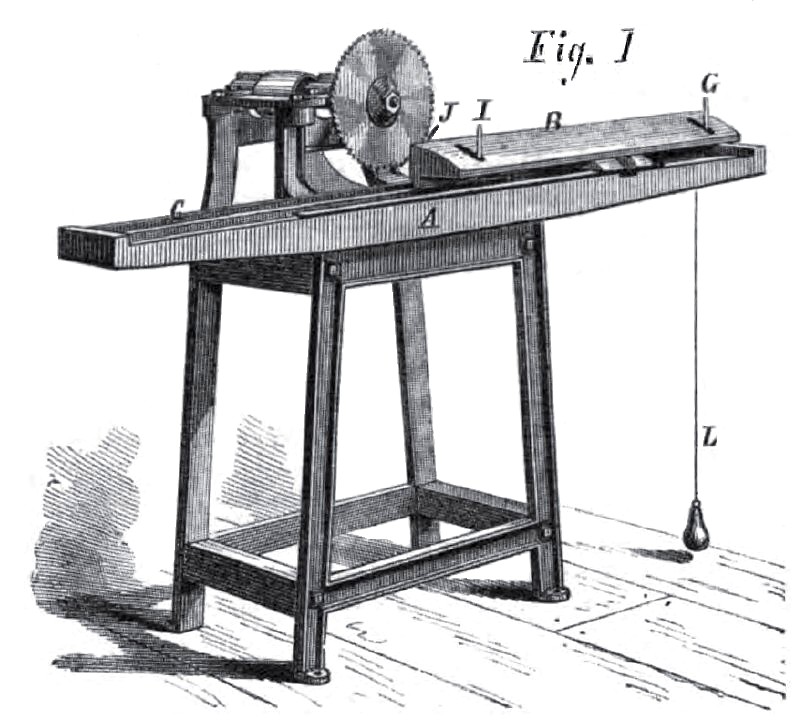
Fig. 1 represents the device as placed on a saw table ready for work. Fig. 2 represents the details of the same. A, in both figures, represents the frame of the carriage ways, and B the carriage. The latter may be rounded on the top to suit the curve of staves cut with barrel saws, or flat, for fiat staves. C, Figs. 1 and 2, indicates horizontally inclined guide ways meeting at D. E is a lever pivoted at F. G, Fig. 1, is a pin rising from the end of the long arm of the lever, E, up through a slot in the carriage.
Now, as the lever, E, is also joined to a lever, H, Fig. 2 (where the carriage is shown bottom side upward), the arms of which lever are of the same length as those of E, it is obvious that any movement of the pin, G, will also produce an equal movement, in the same direction, of the pin, I, Fig. 1, which rises from the end of the long arm of the lever, H, through a slot in the carriage, the same as the pin, G.
Thus the two pins move laterally in the same direction and to the same extent, when a stave is placed against them. At the same time the carriage guide ways, C, Fig. 2,are adjusted to give the proper curvature to the edge of that particular stave. The stave, therefore, has only to be laid upon the carriage in the proper position to be jointed. In doing this, the pins are moved by the edge opposite that presented to the saw, and the guideways are correspondingly adjusted.
A spur, J, Fig. 1, holds the end of the stave which is remote from the operator.
The adjustment of the carriage ways remains to be described.
When the carriage is brought into the position shown in Fig. 1, the lever guide pins, G and I, being left free to move, the end of the long arm of the lever, E, Fig. 2, enters a recess in the end of the lever, K, Fig. 2, being guided thereto by a weighted cord, L, attached to it, which cord runs over a pulley, M, in the recessed end of the lever, K. The lever, E, thus engages the lever, K, and causes it to shift the guideways, a ratchet and pawl (not shown) holding the guideways in place till the cut is made, when the pawl is automatically disengaged on the return of the carriage.
The device is capable of adaptation to any saw table, by slight modifications.
Many testimonials certifying to the value of this machine have been shown us, as coming from practical men who have them in use.
Any desirable bilge may be given to casks or barrels by its use, and it can be applied to the jointing of any kind of staves, large or small, curved or straight. The machine is cheap, and will, we believe, meet a long felt want on the part of stave manufacturers.
Patented August 8, 1871, by Lemuel R. Palmer, whom address, for further information, Belfast. Me.
Patent #118,387 |
|
 1872 Lemuel R. Palmer, Stave Jointing Machine
 1872 Lemuel R. Palmer, Stave Jointing Machine (Bottom of Carraige)
|
|