|
Title: |
1872 Article-Riehlé Bros., Testing Machine |
|
Source: |
Scientific American, V 26 #14, 30 Mar 1872, pg. 208 |
|
Insert Date: |
3/8/2013 1:43:52 PM |
Machine for Testing: the Strength of Metals, Wire, Rope, Chain, Cast Iron Columns, Bridge Bolts, and Boiler Plates.
The present age is one in which only accurate knowledge can insure advancement. Experimental methods, having proved their superiority in the attainment of accurate knowledge, are constantly growing in favor. No matter to what extent mathematical theories may be applied to the computation of the strength of building materials, there are so many varying conditions which cannot be formulated that only actual test can determine the strains to which such materials can be safely subjected. There have been numerous testing machines constructed, but many have been cumbersome, and some so inaccurate as to prevent that refinement which should characterize every scientific experiment. We recently illustrated and described a refined arrangement calculated to insure the desired delicacy in this kind of tests, and we herewith give an engraving of still another, which, having been for several years in use, and having, we are told, been subjected to frequent comparison with what is known as the “Government machine,” as well as those manufactured by other parties, has given entire satisfaction.
It is claimed for this machine that it possesses great strength, combined with much simplicity and accuracy, and that it can be furnished at less cost than other machines of corresponding capacity.
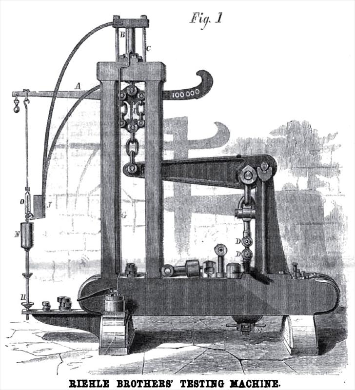
Its construction will be readily understood on reference to the accompanying engravings, the largest of which represents a machine of 100,000 lbs. capacity.
The crane beam, A, Fig. 1, is suspended from the hydraulic jack, B, by a yoke, C, and connected with this small end of the main lever by a clevis and fulcrum. The piece for testing is placed in the clutches at D D. All the bearing parts of the machine rest upon steel knife edges, and when ready for operating, the whole machine is in perfect equipoise, and so nicely adjusted that a half ounce weight placed upon the weight dish will, it is stated, turn the beam. Before the strain is applied, the slack is taken up by means of a screw and a nut at E; the beam is then raised by the jack and pump. The pump, is connected by the tube, G G, to the jack, and as the strain is applied, the beam is kept in equilibrium by placing weights on the dish, at H. The indicating finger, I, vibrates freely in the slotted place in the crane beam. Now, as the crane beam is placed between the small end of the main lever and the pulling jack, the strain is actually weighed by the beam, and not indicated by pressure in the hydraulic jack, as in some machines. In order to obtain a very accurate result, an ingenious self-feeding arrangement is applied, consisting of a reservoir, J (more clearly shown in Fig. 2), containing mustard seed shot, which is suspended from the jack, B, Fig. 1. A valve, M, Fig. 2, at the base of the reservoir, is opened by a pin attached to the beam rod, when the beam raises, which allows the shot to flow into the cup, N, on the beam rod. This cup, N, is suspended to a spring balance, O,which is secured to the rod. When the test piece breaks, the beam falls, and the small valve, M, closes, stopping the
flow of the shot. The weight of the shot poured into the cup, N, is seen on the dial, which is marked in such a manner as to indicate twenty-five pounds (or even less, to ten or fifteen pounds, if necessary).
This machine, without the last improvement, is in successful operation in a number of places, and gives, as above stated, the most unqualified satisfaction.
The two figures, marked D, Fig. 1, represent a grip or vise, that holds the steel in a particularly firm manner, causing a fair and square break, and a correct test. In each end of the test pieces is bored a one and three eighths inch hole, and the piece is placed in the clutches with the thimble lightened up by the bolt which passes through, having a head and nut pressing on each side, so as to prevent bending of any kind. This system of combining a crane beam, with levers, hydraulic jack, or screw, can be adapted for testing material of any description and of any desired form—tensile strength of bridge bolts, rope, wire, chain of any required length; traverse strain for girders, etc., crushing strain for columns, specimens of metals, stone, etc., as also for torsional strain.
For further particulars, address Riehlé Brothers, Ninth and Coates Streets, Philadelphia, Pa., or 93, 95 and 97 Liberty Street, New York City, Ny. |
|
 1872 Riehlé Bros., Testing Machine
 1872 Riehlé Bros., Testing Machine Samples
|
|