|
Title: |
1872 Article-T. M. Chapman, Saw Filing Machine |
|
Source: |
Scientific American, V 26 #12, 16 Mar 1872, pg. 182 |
|
Insert Date: |
3/8/2013 8:45:43 AM |
CHAPMAN’S IMPROVED SAW FILING MACHINE
The original filing machine, herewith illustrated, has been before the public for twenty years, and is familiar to the majority of American lumber manufacturers. The improved machine, which forms the subject of the accompanying engraving, is the result of practical knowledge gained during the period named, the improvements being numerous and important. The machine, as it is represented in our engraving, still retains the best points of the old machine, although the changes are so great that the machine may be said to be entirely remodeled.
The present machine is made wholly of iron, and is much more compact than the old one. The clamps are peculiarly formed, being adjustable and adapted to filing all styles and sizes of saws in common use. By means of the swinging frame described below, all kinds of files may be used, and can be easily and quickly exchanged. Both ends of the file are held, and thus the file is guided evenly and straight across the saw tooth, so that any person, however unacquainted with saw filing, may manage this machine. A peculiar arrangement of the connecting rod causes the file to traverse much more rapidly on its return stroke than in making its forward stroke, the motion thus produced simulating, in this respect, that of the file in filing saws by hand.
A simple and cheap appurtenance, consisting of an emery wheel and proper supporting devices, may be attached at the option of the purchaser, and answers the purpose secured by the more costly ones now in use.
It is claimed that, with this machine, one man can do three times the work that can be done by hand, doing it better, and with a less number of files, than would be consumed in doing the same work by manual labor.
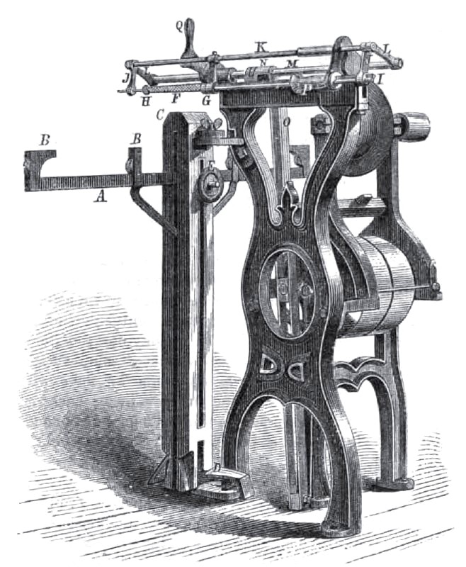
Referring now to the engraving, A is a bar, which supports the back of the saw. This bar is provided with guides, B, at the bottom of, each of which is a roller. The bar, A, is supported, as shown, between the two parts of the clamping vise, C. The inner part of this vise rests upon a pivot at the bottom. It is pivoted at the top. a small graduated arc and pointer enabling the entire clamping device to be set at any required angle, to give the proper bevel to the saw teeth; when thus adjusted, it is held by a set screw. It is instantly clamped by the foot lever, D.
The height of the guide bar, A, is regulated by the set screw. E, which is adjustable in the longitudinal slots of the two parts of the clamping vise. The file, F, has its shank inserted at G, and its point is held at H. It is held by adjustable devices, so that different sizes of files may be used; and being placed as shown, is reciprocated through the rod, I, the arms, J being connected with the rod, K, which is pivoted to the arms L, the latter being fastened to the rod, M. The rod, M, is reciprocated by the collar, N, the latter being actuated by the oscillating bar, 0. The bar, 0, is oscillated by a crank pin taking its motion from the pulley shaft, and impelling a sliding block in a longitudinal slot formed in the bar, O. lt is by the latter means that the quick backward motion, as compared with the forward motion of the file, is secured. It will also be seen that the rods, I,K, M, reciprocate together. But the rod, I, has V shaped grooves, in which slide suitable ways formed in the handle, P. This handle docs not reciprocate, being held by a device for that purpose. It may, however, be rotated, and when so rotated by the hand of the operator, it holds the file in the proper position to act properly upon the saw tooth.
The handle, Q, does not reciprocate, but through suitable devices it is used to rotate the rod. M, on its longitudinal axis; and in so doing, it will raise the file clear of the teeth during the advance of the saw, and, by reversing the motion, lower the file to its proper position for filing again. Both this movement and the one previously described may be made without stopping the reciprocation of the file, and thus the work can proceed rapidly and be performed with superior accuracy.
The machine is, as will be seen, very compact and substantial. The attachment of the emery wheel is shown in the engraving, and needs no particular comment, except that as we have remarked above, it saves the increased expense of a costlier device.
The improvements described were patented through the Scientific American Patent Agency, January 30, 1872, by T. M. Chapman, whom addresses for further information at Old Town, Maine.
Patent #127,462 |
|
 1872 T. M. Chapman, Saw Filing Machine
|
|