|
Title: |
1872 Article-Davis & Canavan, Fitts' Road Steam Traction Engine |
|
Source: |
Scientific American, V 26 #6, 03 Feb 1872, pg. 79 |
|
Insert Date: |
3/5/2013 8:05:39 PM |
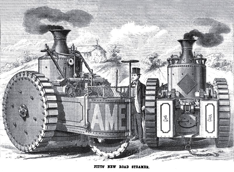
THE ROAD STEAMER “AMERICA”
The engraving which forms our first page illustration this week is an excellent representation of a new road steamer, invented by Mr. George W. Fitts, and upon which three patents have been granted, dated respectively Feb. 28, 1871,0ct. 17, 1871, and Aug. 8, 1871.
There are many good points in the design of this road steamer, aside from the peculiarities upon which the patents are based. The diameter of the driving wheels of the locomotive, represented with side plates and rubber blocks in plan, is about 66 inches over all. The diameter of the guide wheel is 31 inches. The boiler is 38 inches in diameter by 6 feet 6 inches in length. The total length of the machine is about 10 feet. The extreme width of track is 76 inches. The breadth of the faces of the driving wheels is 10 inches and that of the guide wheel 6 inches. The capacity of the water tank is 250 gallons. The fuel bunkers carry hard coal for ten hours labor. The cylinders are 7x12 inches. The total weight is from 7000 to 8,000 lbs.
The structure of the driving wheels and the guide wheel (with the mechanism for operating the latter) being the most prominent features of the locomotive, we will first notice them in connection with Figs. 2 and 3, which illustrate their details.
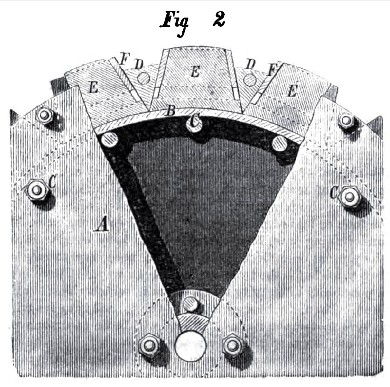
Fig. 2 is a side elevation of one of the driving wheels with a portion of the side plate broken away to show its construction.
The side plates, A, are bolted to the hub of the wheel, as shown. B is a rim supported by the bolts, C, the latter also holding the two side plates of each wheel together. These side plates are also braced between the rim and the hub, and they extend out beyond the rim, as shown. The space exterior to the rim, O, and enclosed laterally by the side plates, A, is divided into chambers or pockets by triangular partitions, D. The pockets thus formed are larger at their base on the rim, C, than at the outer edges of the side plates. In them are placed blocks of elastic rubber, E. Around the outer extremity of each rubber block is placed a band or cap, F, corresponding in shape to the part of the rubber block enclosed. The inner portion of this band or cap is enclosed in the pocket, from which, on account of the inclination of the sides, it cannot escape.
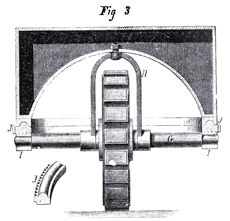
These wheels are driven by gear wheels attached on their inner aides, ea shown in Fig. 1. The steam cylinders are placed to the rear of the axle and above it, and the connecting rods pass over the axle to cranks in front of the axle, on the shaft of which are pinions which mesh into the gears that turn the driving wheels. The guide wheel (front view) is shown in Fig. 3. The general construction of the wheel is like that of the driving wheels, with side plates, triangular partitions, pockets and rubber blocks. Its axle, G, has a yoke, H, attached near the wheel, the yoke being pivoted at the top to the framework of the machine. The boxes, I, of the axle are bolted to the under aide of a toothed circle, J, which corresponds in its action to the fifth wheel of ordinary vehicles. This circle is made convex on the top, its convexity fitting a corresponding concavity in a fixed circle, which guides it in its movement about the central vertical axis. The pivoted yoke prevents the displacement of these two parts. A pinion, K, meshes into the toothed circle, and is actuated, in steering, by a vertical shaft and hand wheel.
The general arrangement is more compact than that of other road steamers before the public, and is of such a form as will admit of its being constructed very light or very heavy, as may be desired; at the same time it is claimed that it retains all the necessary points for a successfully work machine. It is built with special reference to its adaptation to all the various uses to which a self-moving power may be applied, and it is claimed that it can be used, and is as well adapted for a local or stationary power as it is for a moveable one, as by simply blocking up the driving wheels they may be used as band wheels for sawing wood, thrashing grain, shelling or grinding corn, or for any purpose where a stationary power is needed.
The driving wheels are, we believe, an entirely new invention. From actual trial the inventor considers them as good, if not the best, traction wheels that have been constructed. The points of merit claimed for this wheel are its great strength and lightness, the arrangement of the blocks of rubber in the face of the wheel to get the elasticity so much needed in a machine of this kind, combined with the most effective traction surface, its simplicity of construction, and the arrangement of the triangular partitions, by which any of the rubber blocks may be removed and repaired by simply unscrewing a nut and removing the bolt which holds the partition in place, so that, if any part of the wheel or blocks should be damaged, it may be repaired without interfering with any other part of the wheel, thus making the cost of repairs much less than with other forms of rubber tired wheels.
It is claimed that, in the peculiar construction of the guide wheel, a superior advantage in compacting the entire machine is attained, as this wheel may be placed in any desired position under the water tank and entirely out of the way.
The machinery is all thrown around the boiler and directly upon the driving wheels by placing the cylinders upon one side of the axle of the drivers and gearing upon the opposite side, and we believe this is the only machine where this is accomplished.
The boiler is fed by a small steam pump which is placed upon the top of the tank, and is used for a variety of purposes, such as feeding the boiler, filling the water tank by attaching a hose pipe and throwing one end into a pond or well, etc. It will draw the water from the water tank and force it through the same pipe to the height of sixty or seventy feet. Thus it may at times be useful in putting out fires, washing, sprinkling, etc. It works entirely independently of the engines.
It is confidently expected by the manufacturers of these road steamers that they will be able to demonstrate its adaptability to travel upon common roads, and its usefulness for all the purposes for which traction engines are needed.
A machine from which our engraving is taken has been built; and for further information the reader is referred to Davis & Canavan, care of Davis & Foulke, 24 South Front street, Philadelphia, Pa.
Patent #'s 112,135; 117,759 & 119,922. |
|
 1872 Davis & Canavan, Fitts' Road Steam Traction Engine
 1872 Davis & Canavan, Fitts' Road Steam Traction Engine Driving Wheel
 1872 Davis & Canavan, Fitts' Road Steam Traction Engine Guide Wheel
|
|