|
Title: |
1916 Article-Brayton Petroleum Engine Co., Brayton Two-Cycle Gas Engine |
|
Source: |
The Automobile, 23 Mar 1916, pgs. 548, 549 & 560 |
|
Insert Date: |
2/20/2013 1:53:15 PM |
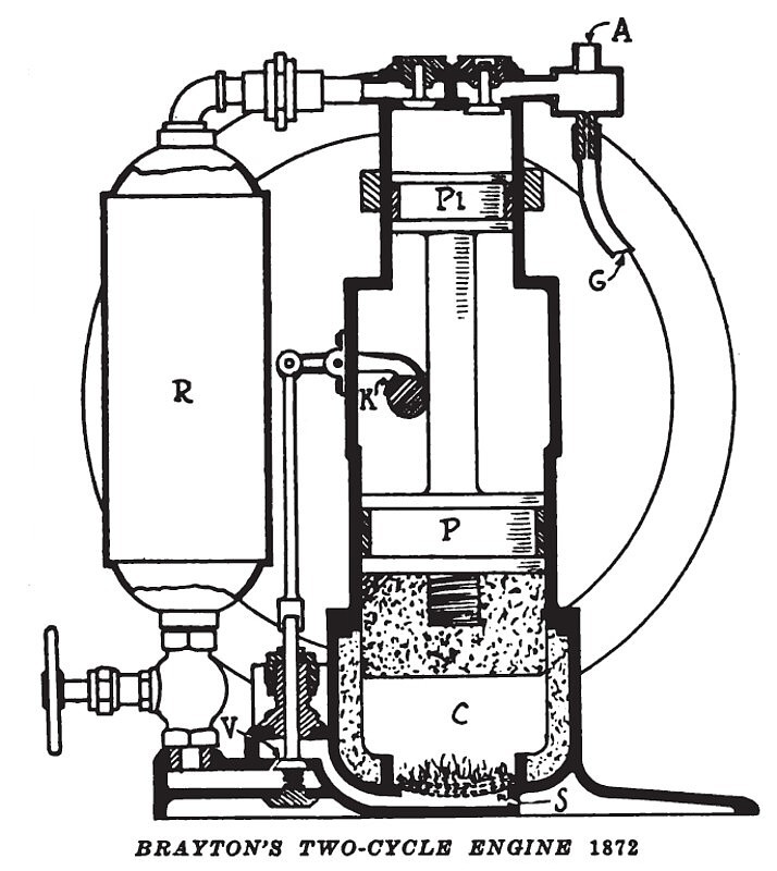
This engine with a single vertical cylinder used a compound piston, the lower portion P known as the working piston, and corresponding with the piston in a gasoline engine to-day and the upper portion PI serving as an air pump to pump a mixture of air and an explosive gas into the larger reservoir R where it was stored under 60 pound pressure. The reservoir was of approximately double the capacity of the cylinder. From this reservoir gas was admitted into the combustion chamber C through a poppet valve V. This valve was opened by the cam K through the medium of a rocker arm and vertical tappet. In the bottom of the combustion chamber C was a series of five or six thicknesses of wire mesh covering the large opening in the cylinder base. The mixture of air and gas entering the cylinder under pressure had to rise through these meshes. Above the meshes was kept burning a constant flame and which ignited all of the incoming gas. The piston P was driven upwards by the expansion due to the neat from the burning of the gas rather than from any explosion. The air pump piston PI drew a mixture of air in through the opening A and the mixture of illuminating gas or some hydrocarbon vapor through the opening G. These were drawn in at the ratio of 12 volumes of air to 1 volume of explosive gas. In the top of the cylinder were the usual valves for regulating the openings between these pipes A and O and the reservoir R. Owing to the constant fire in the bottom of the cylinder it was necessary to carry on the bottom of the piston a substance such as soap stone capable of sustaining a high degree of heat without injury. The combustion chamber was also lined with a similar material. The illustration does not show the engine as being water-jacketed but in actual use it was water-jacketed.
BRAYTON'S TWO-CYCLE ENGINE 1872
This engine with a single vertical cylinder used a compound piston, the lower portion P known as the working piston, and corresponding with the piston in a gasoline engine to-day and the upper portion PI serving as an air pump to pump a mixture of air and an explosive gas into the larger reservoir R where it was stored under 60 pound* pressure. The reservoir was of approximately double the capacity of the cylinder. From this reservoir gas was admitted into the combustion chamber C through a poppet valve V. This valve was opened by the cam K through the medium of a rocker arm and vertical tappet. In the bottom of the combustion chamber C was a series of five or six thicknesses of wire mesh covering the large opening in the cylinder base. The mixture of air and gas entering the cylinder under pressure had to rise through these meshes. Above the meshes was kept burning a constant flame and which ignited all of the incoming gas. The piston P was driven upwards by the expansion due to the neat from the burning of the gas rather than from any explosion. The air pump piston PI drew a mixture of air in through the opening A and the mixture of illuminating gas or some hydrocarbon vapor through the opening G. These were drawn in at the ratio of 12 volumes of air to 1 volume of explosive gas. In the top of the cylinder were the usual valves for regulating the openings between these pipes A and O and the reservoir R. Owing to the constant fire in the bottom of the cylinder it was necessary to carry on the bottom of the piston a substance such as soap stone capable of sustaining a high degree of heat without injury. The combustion chamber was also lined with a similar material. The illustration does not show the engine as being water-jacketed but in actual use it was water-jacketed.
This installment brigs us to the engine patented and built by George B. Brayton of Boston, Mass. The patent was taken out April 2, 1872, and the engine known as the Brayton was the popular and accepted type from that date until 1880 or later. Brayton had been working on his engine for over 20 years; in fact, from a few years after Stuart Perry issued his patents.
It was in connection with the final settlement of the famous Selden patent suit in January, 1911, that the public got its first general introduction to the Brayton engine. The judges in that decision stated that George B. Selden based his patent on the Brayton engine which naturally Selden thought would be the eventual one for all automobile uses. Later events proved otherwise, and that the Otto design, which will be described later, was the real pioneer of the present explosion engine as we know it to-day. Had Selden selected the Otto design instead of the Brayton the American automobile industry would to-day unquestionably be paying its royalties. However, Selden in selecting Brayton in preference to Otto took the wrong direction, and while his patent was declared valid by the courts in 1911 it was also decided that the present type of explosion engine used in automobiles did not infringe it, rather that our engine to-day sprang from the Otto type.
Before describing Brayton's engine we should first realize that it was not an explosion engine as we understand it to-day. It is true Brayton ignited a mixture of air and a combustible gas, the mixture being a 12-to-l ratio, but Brayton in his patent makes it particularly plain that the expansion in his cylinder was not an explosive force on the piston, but "a true pressure due to expansion on account of the fact that the piston is at the very commencement of its stroke when the expanding gases begin to act upon it." Brayton had the idea that the pressure as obtained in steam engines was the one for explosive engines.
Further: Brayton did not employ a carbureter device such as we understand it, but rather used a storage tank in which he mixed the air and gaseous vapor. He pumped them into this storage tank and kept them under pressure. He then let this explosive mixture flow into the working cylinder under its own pressure. As soon as the mixture entered the bottom of the cylinder it was ignited by a flame which kept burning all of the time. He did not have ignition as we understand it, but simply a constant-burning flame. Brayton had a regulated intake valve much as we understand it which controlled the entrance of the explosive mixture into the cylinder. This valve was opened and closed by a combination of cam, tappet, and springs, quite similar to systems employed today.
Brayton had to have with his engine an air pump which kept the reservoir filled with a mixture of air and explosive vapor under a uniform pressure. This air pump was really a part of his motor so that the piston of the air pump was really a continuation and integral portion of the piston in the working cylinder.
Not Strict Explosion Engine
It will thus be seen that although Brayton's engine proved a popular one in the 70's and gave every indication in those days that it might develop into the possible engine to be used on automobiles, still it was not a strictly explosion engine, but bore a striking resemblance to steam in that the charge of air and gas was carried in a separate reservoir to be drawn upon as necessary, just the same as steam is carried under pressure in a boiler and drawn upon as needed. Brayton did, however, get away from one feature of steam, namely, he used a single-acting piston; that is, the explosive mixture was admitted at one end of the piston only as is done to-day. Steam engines are double acting; that is, the steam enters at each end of the piston, and up to Brayton's time all inventors of explosion or gas engines used the double-acting system. Brayton thus marks the first radical step in departure from the double-acting engine to the single-acting engine of this date.
Brayton's engine was constructed in a thoroughly mechanical manner, and was unquestionably the best explosion engine yet produced. It, therefore, began to win approval wherever shown and one was exhibited at the Centennial Exposition in Philadelphia in 1876, where it was utilized to pump air for the Aquarium.
A section of the Brayton engine illustrated herewith shows its general scheme of operation, with its compound piston, the lower portion P forming a working piston and the upper portion P I being an air pump to store the mixture of air and explosive gas in the reservoir R under a pressure of 60 lb. The crankshaft does not appear, but how the engine was worked out can be judged from an external view of it, also shown. A very large-diameter flywheel was used. The mechanically operated intake valve V opened by the cam K through a rocker arm and tappet appears. The spring to close the valve is also shown. When this valve was opened the mixture from the reservoir R immediately rushed in to fill the space C below the piston, but on entering the piston through the large opening at the base it had to pass through five or six fine mesh screens. Above these screens was a constant ignition flame, also supplied with
gas from the reservoir R. Thus the gas rising through the screens or mesh started burning and it was this burning coupled with the pressure of the gas that raised the piston. There was not any sudden explosion as we know to-day, but rather Brayton relied on the expansion due to the heat from combustion.
When starting the engine it was first necessary to open the throttle wheel shown below the reservoir R. The constant flame for ignition was next ignited. This done, the large flywheel was turned over by hand until the valve V opened. The in-rushing gases then began burning and the pressure lifted the piston. The momentum of the flywheel was then sufficient to carry the piston down until the valve V was again opened. Thus the cycle of operation was continued. There was no cycle of operation, as we know it to-day, that is, induction, compression, explosion and exhaust. There were but two cycles, combustion and exhaust. When the engine had to be stopped the hand throttle wheel was turned, shutting off the supply of mixture from the reservoir R. The heat expanded the air to a much larger volume so that although working at a pressure no higher than the air pump pressure it, because of the larger piston area and larger volume, would not only drive the air pump piston but yield considerable power available for work besides.
Used Accurate Oil Pump
Brayton developed an oil pump that, although not of delicate construction, permitted accurate adjustment of the oil supply and to a large extent governed the engine by varying the amount of oil admitted. His great problem, of course, was to get a proper mixture and to continue the combustion from one admission of air to the next. His
structures show evidence of much work along these lines. In some cases the air and liquid passed through wicks much as were employed in kerosene lamps. In others, the oil was thrown on several layers of woven wire through which the air was obliged to pass and which wire by its heat absorbed from the flame of combustion quickly vaporized the liquid. The ignition was originally started by applying a torch to a peep-hole after a plug had been removed, the plug being quickly inserted thereafter. That the flame might continue from one combustion period to the next a very slight by-pass hole was provided in the inlet valve or near it so that a little fresh air from the air tank continually flowed. This resulted in a little waste of air and fuel during the exhaust stroke, but there would be enough fuel left in the wick or gauze between admissions to burn with this air and keep a small flame alive until the next entrance of air and fuel.
Experience showed that the composite layer of gauzes gave better results if one or more of the wire sheets were perforated so that the air could pass through more freely at the perforated point. This arrangement insured some variety to the mixture, in that it would be more nearly pure air where the perforations were and much more nearly all vapor at the edges of the wire layers where they were held in the cylinder walls and therefore much cooler and more slow in vaporizing the fuel. The result of this arrangement was that it
was practically certain a combustible mixture of air and vapor would exist at some point between these extremes and this insured the flame being continuous and the engine certain in operation.
Brayton's engines were frequently built in two cylinder form and up to 40 hp. Like all engines of that day they were neither high-speed nor lightweight as modern ideas go, but they were really very creditable creations.
In 1873 Brayton arranged with a street car company at Providence, R. I., to apply his engines to one of its cars, but the city authorities refused to allow the car to run on the streets by its own power unless horses were attached to it, so most of the use and testing given the car took place on a short private length of track near a fair ground, after which the experiment was abandoned. In 1876 he licensed Joshua Rose and A. R. Shattuck to make road vehicles driven by his engines.
At Philadelphia a James Fawcett of Pittsburgh, operating bus and hack lines in Pittsburgh, saw the Brayton engine, talked with Brayton and decided to equip an omnibus with this form of power, which was done in 1878. The first form of transmission being a hydraulic one and proving unsatisfactory, the engine was remounted with shaft projecting toward the rear and with bevel gear to drive a cross-shaft. A friction clutch and reversing arrangement were also provided, but like the streetcar, the project had to be abandoned because the city authorities would not permit its use. |
|
 1872 Brayton Petroleum Engine Co., Brayton Two-Cycle Gas Engine
 1872 Brayton Petroleum Engine Co., Brayton Two-Cycle Gas Engine
|
|