|
Title: |
1894 Article-Sharp, Stewart & Co., Ltd., Metal Planing Machine |
|
Source: |
Engineering Magazine, V 57, 12 Jan 1894 pg. 46 |
|
Insert Date: |
2/18/2013 1:38:06 PM |
PLANING MACHINE WITH ROBINSON AND OLDFIELD'S FEED MECHANISM
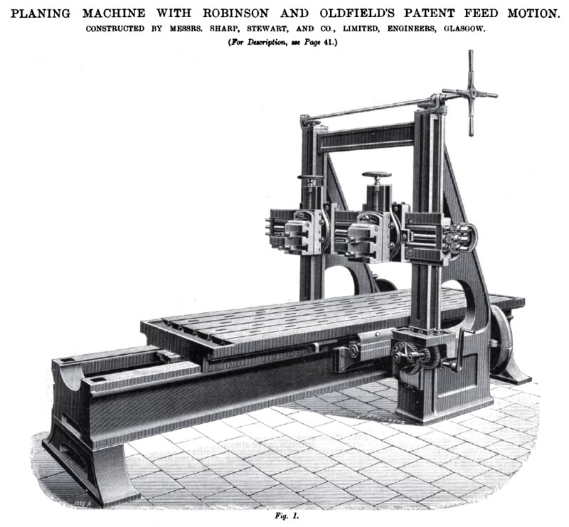
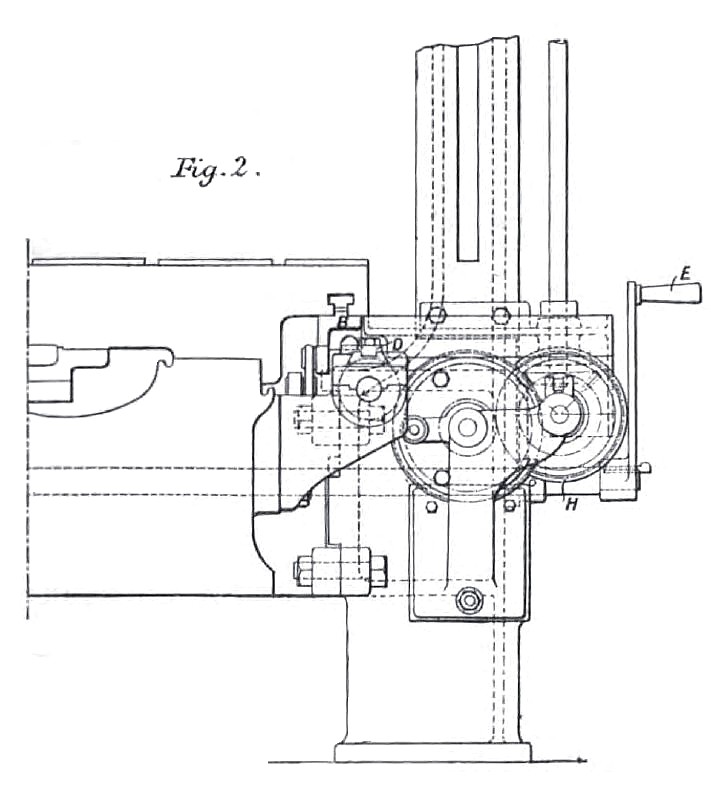
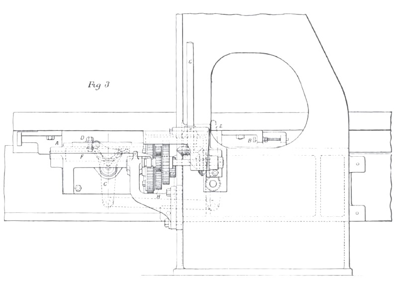
The planing machine which we illustrate on page 46 (Fig. 1) has been constructed by Messrs. Sharp, Stewart, and Co., of the Atlas Works, Glasgow, and in general design is similar to the machines made by this company for a number of years. This is in particular the case with the driving gear, which consists of a rack below the table, gearing with which is a pinion having helical teeth. The teeth are machine-cut, and a very smooth motion is attained. The wear also is small, as, though upwards of one thousand machines with this type of gear have been supplied by the company, in no instance have they yet had to replace either wheel or rack. The machine is very rigidly constructed, and it is claimed that higher speeds than were formerly possible can be attained in both the cutting and return strokes, there being an entire absence of shock and vibration. Its feature of special interest is, however, the feed motion (Robinson and Oldfield's patent) with which it is fitted, the arrangement of which is shown in Figs. 2 and 3. In this A and B represent tappets attached to the table of the machine in such a way as to strike the reversing lever C (Fig. 3), and the feed tappet D, which are perfectly independent of each other, thus reversing the machine and actuating the feed mechanism at the same time. Owing to this arrangement, the machine can by means of the handle be stopped, started, or reversed without moving the feed gear at all. Thus, if any accident happens to the tool, it is only necessary to move the lever E to stop the machine, and there is no risk of putting in a cut accidentally whilst bringing the machine to a stand. The feed tappet D is carried by a slide, and on the top of the stud fixing the tappet there is a hardened steel runner or die, which engages with a helical cam F. As D is moved to the right or left, this cam revolves and actuates the vertical shaft G through the feed gear H. This shaft G operates the feed screws of the tool boxes. The tappet D is adjustable in its slide, and can be arranged to receive an impetus either from A or B, and either sooner or later in the stroke of the table, thereby giving a variable feed, the range being from 1/32, in. up to 1½ in. The change from one rate of feed to another is very quickly made. The feed is "put in "in as short a travel of the table as in the ordinary mechanism, and there is no drag of the tool over the work in the return stroke. The machine shown in the engravings can plane castings, if necessary, 4 ft. by 4 ft. by 10 ft., and the feeds can be given either up or down, right or left, and at any angle. In all cases the feed is "put in" at the end of the return stroke. |
|
 1894 Sharp, Stewart & Co., Ltd., Metal Planing Machine
 1894 Sharp, Stewart & Co., Ltd., Metal Planing Machine
 1894 Sharp, Stewart & Co., Ltd., Metal Planing Machine
|
|