|
Title: |
1888 Article-Aveling & Porter, Compound Steam Traction Engine & Crane |
|
Source: |
The Engineer Magazine,03 Aug 1888 pgs. 92 & 96 |
|
Insert Date: |
1/14/2013 1:43:16 PM |
TRACTION ENGINE AND CRANE
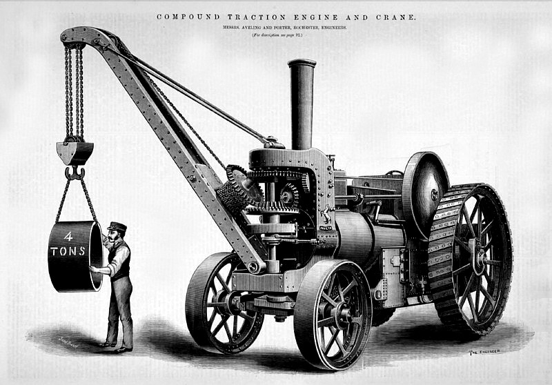
In our notice of the Nottingham Show we mentioned an extremely handy crane shown by Messrs. Aveling and Porter, of Rochester, which had rendered excellent service in unloading Midland Company's trucks at the show yard siding. This crane we illustrate on page 96. Those who go to Royal Agricultural Societies' shows are familiar with the neat little combined traction engines and cranes made since 1870 by the firm. But these cranes could not slew their jibs. In the crane we now illustrate on page 96 this great advantage has been gained by very elegant mechanism.
The crane post is a vertical shaft, standing in front of the smoke box, and the jib can swing round on it in a way that will be readily understood from our engraving. Slewing is effected by means of a toothed sector, to the jib by a bent arm. On the inclined portion of this arm revolves the lifting drum, fitted with a beveled wheel at top. The sector gears with a worm on a transverse horizontal shaft, which is driven from the crank shaft by bevel gear fitted with a friction clutch which lies behind the framing carrying the crane post, and is controlled from the foot plate.
The weight is raised or lowered in the following way:—In the engraving it will he seen that the hoisting drum carries, as we have said, a bevel wheel. This gears into a pinion, which is cast in one with a sleeve on the crane post. A horizontal bevel wheel lies just below the pinion, and is driven by a suitable bevel pinion, caused to revolve by the crankshaft in a way that does not need description. If now the horizontal bevel wheel can be coupled to the horizontal bevel pinion, the winding drum can be caused to revolve by the crankshaft. Within the thin cheese-shaped piece on the crane post are three discs. The top one is the driving disc, and is cast in one with the horizontal bevel wheel. The middle disc is called the drum disc, and is in one with the bevel pinion, gearing with the winding drum wheel. The lowest is the brake disc, which is fixed to the crane post. The drum disc has a rim on it, seen in the engraving, which rim hides the other two discs, and in this rim are taper wedges moved by the transverse shaft, seen under the disc box, and a sliding collar. If the wedges are pulled down from the footplate, the brake disc is released from the drum disc; but the drum disc is then coupled to the driving disc, and the weight is raised. When it is to be lowered, the wedges are pushed up. The driving disc is then detached, while the drum and brake discs are coupled, and the weight is either held suspended or allowed to fall slowly. The whole arrangement is very elegant, and works admirably.
The crane will lift four tons, and about two tons can be swung at right angles to the engine without risk of overturning it. It us not easy to see how anything more perfectly adapted for general crane purposes can be had. The engine could move along a train of railway wagons, and unload them all one after another, and it is besides a very powerful and efficient traction engine.
Image Courtesy of Grace's Guide
http://www.gracesguide.co.uk/File:Im1888EnV66-p096.jpg |
|
 1888 Aveling & Porter, Compound Steam Traction Engine & Crane
|
|