|
Title: |
1878 Article-Aveling & Porter, 8 H. P. Traction Engine |
|
Source: |
The Engineer Magazine, 18 Oct 1878 pgs. 279 & 286 |
|
Insert Date: |
1/11/2013 8:53:21 PM |
MESSRS. AVELING AND PORTER‘S NEW ROAD LOCOMOTIVE
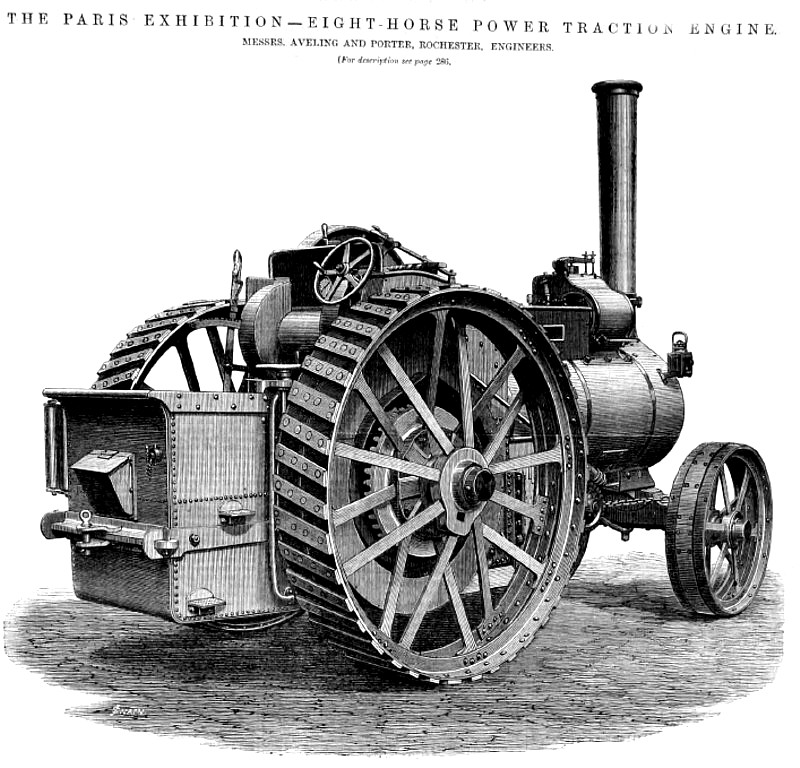
We illustrate at page 279 Messrs. Aveling and Porter's newly-arranged road locomotive. This engine was exhibited at the recent show at Bristol and at the Paris Exhibition, and contains some very valuable improvements.
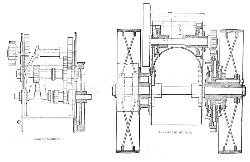
One of the chief features of the engine is the arrangement by which all the gearing with the exception of the pinion gearing with the main wheel, is mounted on shafts between bearings, and not on the overhanging ends of shafts outside bearings. Everyone acquainted with the working of gearing subject to very heavy strains will know how to appreciate this improvement. The difference between the rigidity thus secured is similar to that between the rigidity or resistance to deflection of two similar beams, the one supported at one end and loaded at the other and the other supported at one end and loaded in the middle. Thus the bearings are more fairly worn, and what is of more importance, the gearing is maintained rigidly in truth. Another important gain in the arrangement patented Mr. Aveling is that at the same time small pinions an large spur wheels are alike dispensed with, the employment of an intermediate countershaft, securing the reduction of speed between the crankshaft and the driving wheels without resorting to large differences between the diameters of the wheels, the ratio between the revolutions for the slower traveling speed being as twenty-six to one. The arrangement, though very simple, has taken a long time to arrive at, and could not even now advantageously employed without the system of forming the brackets for the crank and countershafts by carrying up the outside fire-box plates. This was also first adopted by Messrs. Aveling and Porter, and with the arrangement at gearing employed, permits a great reduction in the width of the engine, and both fly-wheel and main road wheels are brought very close up to the bearings, there being, as Mr. Aveling remarks, no "atmospheric" bearings. Referring to the accompanying plan, it will be seen that the two crank shaft pinions, which are fixed, are of the same diameter, and both gear into the same wheel fixed on the long sleeve on the lay shaft, upon which are also fixed the two wheels for transmitting motion to the driving shaft. The sleeve slides on the fixed countershaft, which it may be here remarked forms an excellent stay between the bracket plates, themselves further stayed by cross plates. As shown in the plan and transverse section, the outer wheel is in gear with that on the driving shaft on the left; but by sliding the sleeve over so that the wheel near the crank is put into gear, the engine travels at slow speed. These positions are controlled by the one lever shown, which, when fixed in mid-position, holds the whole out of gear. It will be noticed that the wheels and pinions for one speed cannot he put into gear without first disconnecting the others, and that feathers, one of the moat fruitful sources of trouble, are entirely dispensed with. The gearing is all of crucible steel, all the teeth, except on the wheel in the centre of the
central shaft, are shrouded, and the rings of teeth of the wheels are all cast separately and strongly bolted on the boss part. The castings carrying the bearings of the countershafts and axle are turned on the outside and accurately fitted into holes bored in the side plates, so that it is impossible for them to move, and at the same time very little strain is thrown on the bolts, and the maintenance of the gearing in pitch does not depend upon them. Messrs. Aveling and Porter's long experience in the construction of engines of this class has enabled them to discover the sources of weakness and trouble in their working, and in recently passing through their shops we were enabled to see their engines in different stages towards completion, and to judge of the thoroughness with which the work is done. Every experienced difficulty has evidently afforded a lesson not lost sight of, many of which are embodied in details unseen except in the workshop, but the want of which in generally discovered when furthest therefrom.
To the road locomotive described, the makers are now fitting wrought iron wheels, the rims of which are composed two tee-irons specially designed and of very strong section, the rib being of such a depth that the rivets by which the spokes are fastened thereto, can be placed zigzag, and by which considerable gain of strength is secured. The tee irons are united on their exterior faces by the steel cross bars forming the shoes. Altogether the engine we have illustrated is well and strongly proportioned, and fitted with large surfaces throughout. The driving-wheel, it should be noticed is fitted with a small winding-drum on one side, and is provided with about I00 yards of steel rope for hauling loads or the engine itself out of holes.
It may be interesting to mention that Messrs. Aveling have not a single horse on their works, nor do they employ any, all haulage work being done by one of their engines.
Image Courtesy of Grace's Guide
http://www.gracesguide.co.uk/File:Im1878v46Er-Aveli.jpg |
|
 1878 Aveling & Porter, 8 H. P. Traction Engine
 1878 Aveling & Porter, 8 H. P. Traction Engine (Sectional Views)
|
|