|
Title: |
1895 Article-Charles Burrell & Sons, Ltd., Compound Steam Road Roller |
|
Source: |
The Engineer Magazine, 13 Dec 1894, pg. 579 |
|
Insert Date: |
12/31/2012 10:36:24 PM |
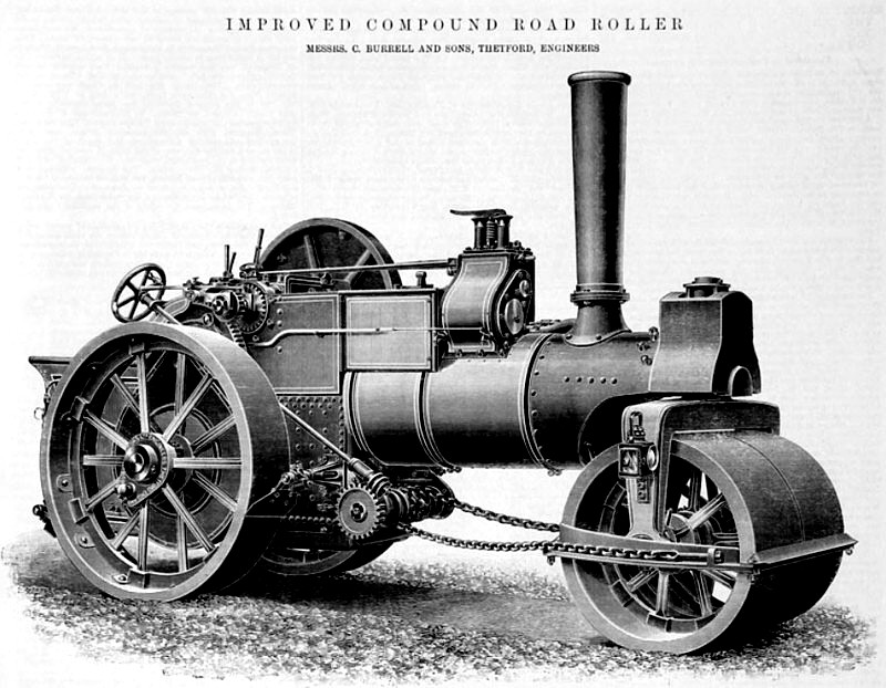
10 TON IMPROVED COMPOUND ROAD ROLLER
We illustrate above Mr. F. Burrellls latest design of compound road roller. The roller shown weighs ten tons. The Improvement consists not only in general design, but in new fore carriage, patented by Mr, Burrell. There is a curved collar ?tted on the lower portion of ths fork stem. This collar is 7in. deep, and the half trunnions ?t into recesses in the saddle casting. ‘The extra bearing surface thus provided reduces all wear and tear to a minimum, and whilst providing a sort of universal joint to ensure a perfect action upon the road, all chance of rattling and shaking in that part when at work is avoided. It will be noticed that the engine is constructed with three shafts only, so as to reduce the friction upon the gearing to the lowest possible amount, and although the total width over the hind: rollers is but 6ft, 3in., the boiler is unusually large in diameter, viz., 2ft. 2¾in. By this means I much larger amount of heating surface than usual is obtained, and plenty of steam room. The heating surface is 101 square feet, and the grate area 4x6 square feet. The hind rollers are 5ft, 6in. in diameter, and the front rollers are 3ft. 8in. in diameter. The front rollers overlap the inside edges of the hind rollers by 4in. on each side, so as to avoid missing portions of the road when rolling curves. The keys upon the crankshaft are out of the solid and case-hardened. The first motion gearing is 2¼in. wide; the last motion gearing is 4in. wide. The material of which the rollers are made is as hard as can possibly be machined, and to ensure soundness the rollers are cast about 8in. wider than the finished width and turned of. These rollers are fitted with compound cylinders upon Mr. Burrell‘s patent single crank system, which admits of the whole space between the horn plates being devoted to bearing surface for one crank only, and which system has now stood the teat of over 300 applications. Great attention has been given to the distribution of weight upon the rollers so as to roll with as nearly as possible equal pressure upon the surface of the road. The smoke-box is not formed by an extension of the boiler barrel as usual, but is enlarged up to the diameter of the lagging and riveted to an extension of the barrel plate through a 2½in. by 1¼in, ring, thus allowing the smoke-box be renewed without disturbing the front tube plate. The smoke-box plate is carried forward and bolted by radial bolts to the fore carriage top casting, this construction giving a maximum of strength and dispensing with the heavy saddle commonly in use, the chimney base being a separate casting. Advantages have been claimed for the first motion gearing between the brackets, but it is impossible to get the first motion between the brackets, and since there is about six times the strain accumulated between the last motion centres as between the first motion, there is obviously little in it. Messrs. Burrell have entirely abandoned the four-shaft design for rollers in place of three-shaft, simplicity of construction being the first consideration. The machines and the workmanship of the rollers fully maintain the high reputation of the firm.
Image Courtesy of Grace's Guide
http://www.gracesguide.co.uk/File:Im1895EnV80-p579.jpg |
|
 1895 Charles Burrell & Sons, Ltd., Compound Steam Road Roller
|
|