|
Title: |
1915 Article-John Fowler & Co., Oil Fired Steam Roller |
|
Source: |
The Engineer Magazine, 26 Feb 1915, pgs. 212 & 213 |
|
Insert Date: |
1/3/2013 4:52:42 PM |
TWELVE-TON OIL-PROPELLED ROAD ROLLER
The application of the internal combustion engine to the propulsion of road rollers of moderate weight is not new and presents no features of difficulty. For the heavier class of machines, such as that shown in the accompanying illustration, the oil engine has hitherto not often adapted, as far ass we are aware. In the roller under notice, John Fowler and Co. (Leeds), Limited, have made use of the chief features of the paraffin tractor which was described in THE ENGINEER for July 12th, 1912, the leading differences being in the arrangement of the gearing, the absence of springs, the addition of the fore-carriage head and fork. and the scarifier. In other respects steam road locomotive practice has been followed as closely as permissible, as will be noted by reference to the drawings given on page 213.
The engine is of the horizontal pattern, carried in a framework secured to the top of the barrel. It has four cylinders. 6½ in. diameter by 7 in. stroke, arranged in pairs on opposite sides of the crank shaft and capable of developing 50 horsepower at a speed of between 700 and 800 revolutions per minute. The valves are of the vertical type, operated by horizontal camshafts contained in enclosed oil baths formed by the valve casings. The cam shafts are operated by spiral gearing from the crank shaft and actuate the valves by means of plungers and rocking levers. Both the inlet and exhaust valves are contained in separate cages, which are readily removable for grinding-in and inspection. The crank casing is cast in two parts, the lower part forming an oil well, from which the oil is lifted by means of a pump into a reservoir fixed
under the awning, whence the lubricant flows by gravity to the bearings and connecting-rod ends. The surplus oil from the connecting-rode lubricates the piston. In order to indicate to the driver the amount of oil in the system, the reservoir is fitted with an overflow to the crank case and an indicator glass.
The crankshaft is of the double-throw pattern with cranks at an angle of 180 deg., made of nickel chrome steel. The engine is intended for operating on paraffin after being started up on petrol, and with this object the "Davis" carburetor has been fitted with two float chambers, one for each class of fuel. A fly-wheel is fitted on each end of the crank shaft and inside the right-hand wheel a friction clutch of the cone type, and operated by a foot lever, is provided. This clutch enables the motion of the crankshaft to be transmitted to the hind rollers by means of a train of spur gearing, which provides two forward road speeds of 1½ and 3 miles per hour and a reverse motion, the final motion being transmitted through steel pinions on the end of the fourth motion or differential shaft to internal gear rings secured to the rollers. The change-speed gearing is all cut out of steel and enclosed in the engine framing, as shown very clearly in the transverse section. The changes of speed are effected by a single hand lever. In order to ensure a constant speed of the engine when used for belt driving a governor is fitted.
The steerage is of the usual worm-and-wheel type, with chains attached to segments round the front rollers. The fore-carriage head is a large cast iron bracket arranged to fit the barrel, and is designed to suit the fore-carriage fork usually provided on Fowler steamrollers. Both hind and front rollers are fitted with spring scrapers, which are equally effective when the roller is working either forwards or backwards. There are two brakes, one with shoes acting on the inside of the hind roller rims and controlled by a hand wheel and screw, and the other a band brake acting on the drum on the fourth motion shaft, and operated by a hand lever. Both brakes are manipulated from the foot-plate. The roller is fitted with a three-tine Allen scarifier, the stress being taken by the horn plates and hind axle.
The fuel and water tanks are placed inside the locomotive barrel. The radiator is fitted underneath the fore-carriage head, and is thus protected from injury, and the water circulation from the tank to the radiator is effected by a rotary pump. The roller, without the scarifier, weighs about 12 tons.
Image Courtesy of Grace's Guide
http://www.gracesguide.co.uk/File:Im1915EnV119-p212.jpg |
|
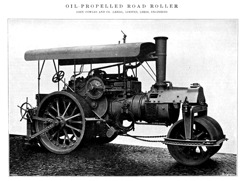 1915 John Fowler & Co., Oil Fired Steam Roller
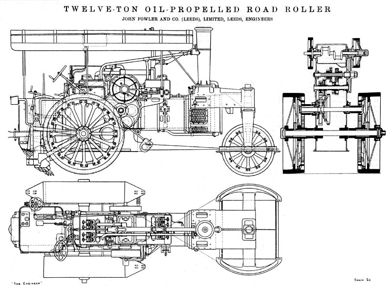 1915 John Fowler & Co., Oil Fired Steam Roller (Sectional View)
|
|