|
Title: |
1900 Article-Alfred Herbert Ltd., Hexagonal Turret Machine |
|
Source: |
English & American Lathes, 1900 pgs. 125 & 126 |
|
Insert Date: |
12/19/2012 8:17:06 PM |
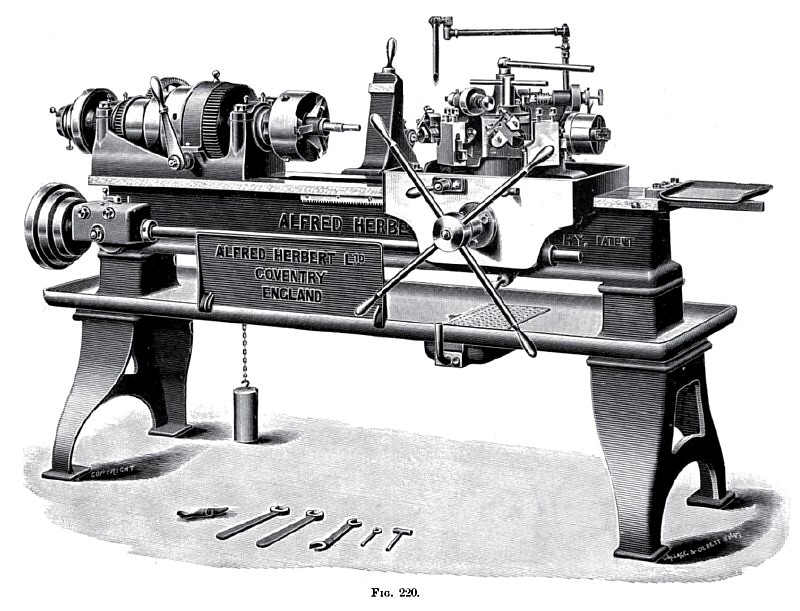
Fig. 220 illustrates a hexagon turret machine, by Messrs. A. Herbert, Ltd., while Fig. 221 shows a portion of it, viz., the turret and chaser in plan, to a larger size. This machine has been introduced to meet the demand which exists for a turret-lathe for general engineering purposes, that shall combine the following features:—
(a) The ability to produce screws, pins, bolts, studs, and turned work generally as expeditiously as on the ordinary turret-lathe, but without the special tools which are always needed by the latter machine, the expense of which is often complained of by engineers who have only a limited number of pieces of a kind to produce.
(b) To enable pieces much longer than those operated on ordinary turret-lathes to be satisfactorily dealt with.
(c) To enable much heavier cuts to be taken than is possible with other machines.
The capacity of the machine can be inferred from the following:—
The largest size of bar which can be admitted through the spindle is 2 in. ; the length of the longest piece which can be produced is 1 ft. 4 in. Threads can be cut with an automatic die-head from 3/8 in. up to 1 in. Other and larger threads can be cut with the chasing-bar.
The headstock is provided with friction-clutches, which permit the back-gears to be thrown in or out without stopping the lathe, by movement of the lever at the front of the head. The turret, seen in plan view, Fig. 221, is of large size, hexagonal in form, and mounted in the centre of the saddle, which latter moves along the bed. This arrangement obviates the overhang of the turret-slide which occurs in the ordinary type of turret-lathe. The hexagonal faces of the turret have recesses bored in them, which receive projecting bosses on the back of the tool-holders. The tool-holders are held in position by four bolts. In addition to the usual tool-holders, holes are bored into the faces of the turret, and are provided with locking pads, so that tools with shanks can also be used if required. The turret is so arranged that long work can be passed entirely through it, thus obviating the overhanging weak tools which are required on lathes with solid turrets which deal with long pieces.
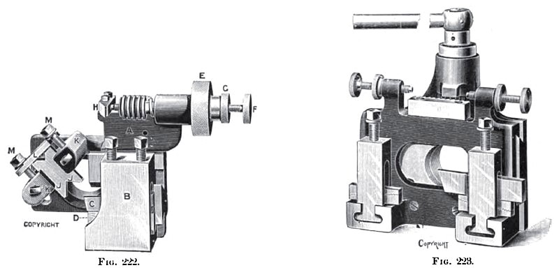
Turning-tools are clearly shown in Figs. 220 and 222. The tool-holder consists of a body A, which is attached to the turret, as previously explained, and which carries in front a planed slide, on which is fitted a steel tool-box B. In this the cutter C, consisting of an ordinary forged tool, which can be readily ground on an ordinary grindstone or emery wheel, is clamped, and is adjustable for height by serrated packing wedges D. The cutter can be moved in or out by means of the knurled knob E, in order to suit work of varying diameter. The adjustable stop F, and locking nut G, controls the movement of the tool, enabling it to be returned accurately to position against the stop H.
In order to support the work, and to enable the heavy cuts required to be taken, adjustable steadies J J are supplied. A projection cast on the body of the tool-holder carries these V-shaped steadies, which are adjustable by means of the plate and screws MM seen at the back, and the swing plate L. This arrangement of tool-holder is so rigid and firm that it permits of 2 in. bars being reduced to h in. diameter at one cut; and the fact of the steady acting as a burnisher, produces smooth and thoroughly well-finished surfaces at the one cut, and as accurate in size as work produced in the ordinary lathe. After the job is completed, the tool is drawn slightly back by means of the adjusting knob E. in order not to mark the finished piece. The stop previously referral to enables it to be returned accurately to position for the next piece. Two of these turning tools are included in the standard outfit of the lathe. so that pieces having different diameters in various parts of their length can be dealt with.
Threads up to 1 in. diameter are cut by means of the automatic, die-head seen in Fig. 220. This die-head cuts the full thread at one travel, and flies open automatically when the desired length has been cut. thus obviating the reversing of the lathe. Threads of larger size than 1 in. are cut by the chasing-bar, controlled by a suitable leader at the back of the headstock. This chasing-bar, when in operation, bears on the bed itself, and is rigid and free from spring. |
|
 1900 Alfred Herbert Ltd., Hexagonal Turret Machine
 1900 Alfred Herbert Ltd., Hexagonal Turret Machine (Top View)
 1900 Alfred Herbert Ltd., Hexagonal Turret Machine Tooling
|
|